
sales@sztimeast.com
+86-15989541416
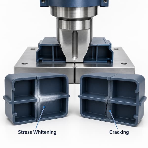
Plastic cracking and stress whitening during ultrasonic welding are usually not caused by one machine setting alone.
They are symptoms of excessive localized stress, uncontrolled energy input, inadequate fixture support, poor joint
geometry, molded-in stress, or variations in the plastic material.
The first step is not to immediately increase or decrease welding time. Engineers should first identify where
the defect appears, when it occurs, and whether the part already contains stress before welding.
This guide explains how to distinguish stress whitening from cracking, identify the most likely root causes,
and troubleshoot the welding process systematically
Plastic parts may turn white or crack when ultrasonic vibration, pressure and heat create more localized stress
than the part can safely absorb.The most common causes include:
Excessive welding amplitude, energy or weld time
Incorrect or unstable welding pressure
Poor energy director or joint design
Insufficient fixture support
Horn misalignment or uneven horn contact
Sharp corners, ribs or sudden wall-thickness changes
Residual stress from injection molding
Moisture, fillers, regrind or material variation
Incorrect welding frequency or control mode for the application
The correct solution depends on the defect location and failure pattern.Reducing one parameter without testing
ultrasonic weld strength may hide the cosmetic defect while creating a weak weld.
Stress whitening is a white, cloudy or frosted appearance that develops when a plastic part experiences localized
deformation.Microscopic deformation, voids or crazing inside the material can scatter light and make the affected
area appear white.The defect is often more visible on dark, transparent or high-gloss plastic parts.
Stress whitening may appear:
Under the welding horn
Beside the weld interface
Around ribs, bosses or sharp corners
Near an energy director
On thin unsupported walls
Around snap-fit or molded features
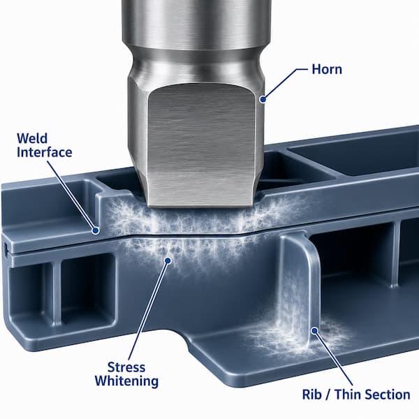
Stress whitening does not always mean that the weld has lost its mechanical strength. However, it indicates
that the part has experienced significant localized stress and that the welding process or part design should
be reviewed.
Stress whitening changes the appearance of the plastic but may not create a complete fracture.
Cracking is more serious. It means the material has separated and may no longer meet strength, sealing, safety or
appearance requirements.
Cracks may occur:
Along the weld line
Through the plastic wall
At the base of a rib or boss
Around a sharp internal corner
At the edge of the horn contact area
Several hours after welding
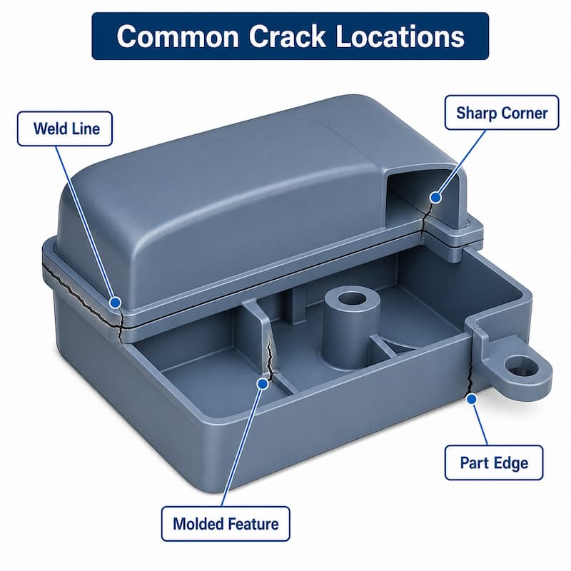
Delayed cracking is especially important. If the part looks acceptable immediately after welding but cracks later,
the problem may involve residual molding stress, material condition or environmental stress rather than only
excessive weld time.
The location of the defect provides useful information about its cause.
White marks beneath the horn often indicate a contact or support problem.
Possible causes include:
Excessive horn pressure
Excessive amplitude
A rough or damaged horn surface
Uneven horn contact
Insufficient support beneath the part
Local bending of a thin wall
Check whether the horn face matches the product contour and whether the fixture supports the part directly
below the horn contact area.
Whitening close to the joint may indicate that the weld is receiving too much energy or collapsing too aggressively.
Possible causes include:
Excessive amplitude
Excessive weld time or energy
Oversized energy director
Excessive joint interference
Poor alignment between the two parts
Insufficient control of collapse distance
The joint should melt progressively rather than collapse suddenly.
Cracks around molded features often indicate stress concentration.
Possible causes include:
Sharp internal corners
Thin-to-thick wall transitions
Ribs positioned too close to the weld
Molded-in stress
Ejection stress
Poor fixture support
Parameter adjustment may reduce the symptom, but the permanent solution may require changes to
the molded part or fixture.
Cracking through or immediately beside the weld line may be caused by:
Excessive energy input
Poor material compatibility
Incorrect joint geometry
Misalignment
Excessive interference
Material degradation
Inconsistent part dimensions
Inspect the fracture surface to determine whether the crack passed through the parent material or followed
an incomplete weld interface.
1. Excessive Amplitude, Energy or Weld Time
Amplitude controls the mechanical movement delivered by the welding horn. When amplitude, energy
or welding time is too high, the joint can heat and collapse too aggressively.
Possible results include:
Excessive melt flow
Flash
Surface marking
Internal stress
Part deformation
Whitening
Cracking
Reducing amplitude or energy may improve appearance, but the weld must still be tested for strength and
sealing performance.Do not adjust several parameters at the same time. Change one factor,
record the result and compare it with the original process.
Both excessive and insufficient pressure can create problems.
Excessive pressure may:
Compress the part before sufficient melting occurs
Deform thin walls
Increase stress around ribs or corners
Leave visible horn marks
Insufficient pressure may:
Allow unstable movement between the parts
Reduce consistent energy transfer
Create localized heating
Produce incomplete or irregular melting
Pressure, trigger force and downspeed should be optimized together rather than treated as separate settings.
A poorly designed joint cannot distribute ultrasonic energy consistently.
Common problems include:
Oversized energy directors
Energy directors with inconsistent dimensions
Sharp joint corners
Insufficient alignment features
Excessive shear-joint interference
Sudden wall-thickness changes
Weld joints positioned too close to fragile features
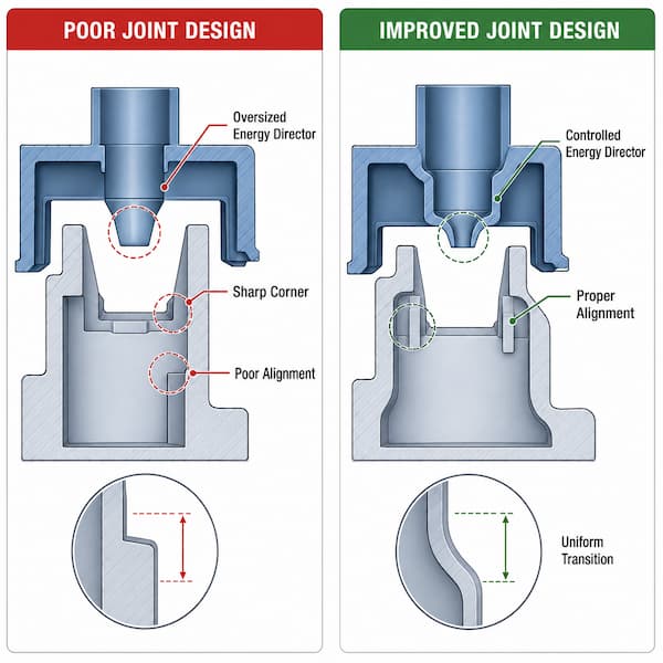
A properly designed energy director should begin melting in a controlled manner and allow predictable
joint collapse. For detailed dimensions, joint types and design principles, see our ultrasonic welding joint design guide. For sealing applications, the joint must also control melt flow without placing excessive stress
on the surrounding wall.
The fixture is not only used to position the product. It must also support the plastic structure against
welding force and vibration.
Insufficient fixture support can cause:
Part flexing
Wall vibration
Local bending
Stress concentration
Energy loss
Cracking away from the weld interface
The fixture should support the part close to the welding area without damaging cosmetic surfaces.
Soft or uneven fixture materials may also reduce process repeatability.
If the horn does not contact the part evenly, one area may receive more pressure and vibration than another.
Check:
Horn parallelism
Horn-to-part contact pattern
Fixture alignment
Product seating
Horn surface condition
Wear or contamination on the horn face
A contact test or pressure-sensitive film can help identify high-pressure areas when appropriate for the application.
The horn geometry, material, surface condition and frequency tuning should also be reviewed as part of the
ultrasonic welding horn design process.
Some parts contain significant internal stress before ultrasonic welding begins.
Common molding-related causes include:
High injection pressure
Uneven cooling
Incorrect mold temperature
Poor gate location
Fast ejection
Sharp corners
Non-uniform wall thickness
Ultrasonic vibration may release or concentrate this existing stress, causing whitening or cracking.
Compare welded and unwelded parts from the same molding batch. If unwelded parts already show distortion,
stress marks or easy cracking, machine settings alone may not solve the problem.
Material name alone is not enough to predict welding behavior.
For example, two parts labeled ABS or PC may behave differently because of:
Different resin grades
Colorants
Flame retardants
Glass or mineral fillers
Regrind percentage
Moisture content
Material contamination
Storage conditions
PMMA is also commonly called acrylic and should not be treated as a separate material category.
Semi-crystalline materials such as PP, PA and POM often require careful control of energy transmission
and joint design. However, they are not automatically more likely to crack than amorphous plastics.
The actual risk depends on material grade, part structure, tooling and process conditions.
| Defect | Likely Causes | First Checks |
White mark under the horn | High contact pressure, excessive amplitude,rough horn face, poor support | Inspect horn contact and fixture support |
Whitening beside the weld line | Excessive energy, aggressive collapse, poor joint design | Reduce energy gradually and check the energy director |
Crack near a rib or boss | Molded-in stress, sharp geometry, unsupported feature | Inspect the molded part and improve local support |
| Crack at a corner | Stress concentration or sudden wall-thickness change | Add radii and review part geometr |
Crack throughthe weld | Over-welding, poor alignment, material degradation | Check collapse, material condition and fracture surface |
Crack appears later | Residual stress, material condition or environmental exposure | Compare molding batches and review storage and service conditions |
One side whitens more than the other | Horn or fixture misalignment | Check parallelism and part seating |
Step 1: Record the Existing Process
Record the current:
Amplitude
Weld time or energy
Pressure
Trigger force
Downspeed
Hold time
Collapse distance
Peak power
Material batch
Part cavity number
Without a baseline, parameter changes cannot be evaluated accurately.
Determine:
Where the whitening or crack begins
Whether every part is affected
Whether the defect is linked to one mold cavity
Whether the defect appears immediately or later
Whether the defect follows the weld line or a molded feature
Photograph and classify each failure mode.
Before changing the welding program, confirm:
The horn contacts the part evenly
The fixture supports the welding area
The part is fully seated
The tooling is aligned
There is no horn or fixture wear
The product does not rock or flex during welding
Depending on the observed defect, evaluate controlled changes to:
Amplitude
Energy or weld time
Welding pressure
Trigger force
Downspeed
Hold time
Collapse distance
For parts requiring tighter dimensional or collapse control, engineers should also compare different ultrasonic welding
control modes, including time, energy, distance and collapse-distance modes.Do not simply reduce all settings until
the whitening disappears. The final process must still meet strength, appearance, dimensional and sealing requirements.
If parameter optimization produces only limited improvement, review:
Energy director dimensions
Shear-joint interference
Alignment features
Rib and boss location
Corner radii
Wall thickness
Distance between the horn and weld interface
A poor joint design cannot always be corrected through machine settings.
Compare different:
Resin batches
Color batches
Mold cavities
Regrind percentages
Moisture conditions
Molding dates
This helps determine whether the defect is a welding problem, a molding problem or a combination of both.
A successful process should be evaluated by more than appearance.
Depending on the product, validation may include:
Visual inspection
Tensile or pull testing
Peel or shear testing
Leak or burst testing
Dimensional inspection
Cross-section analysis
Functional testing
Repeated production trials
Manufacturers developing a new application can follow a structured ultrasonic welding validation process before
purchasing equipment or starting mass production.
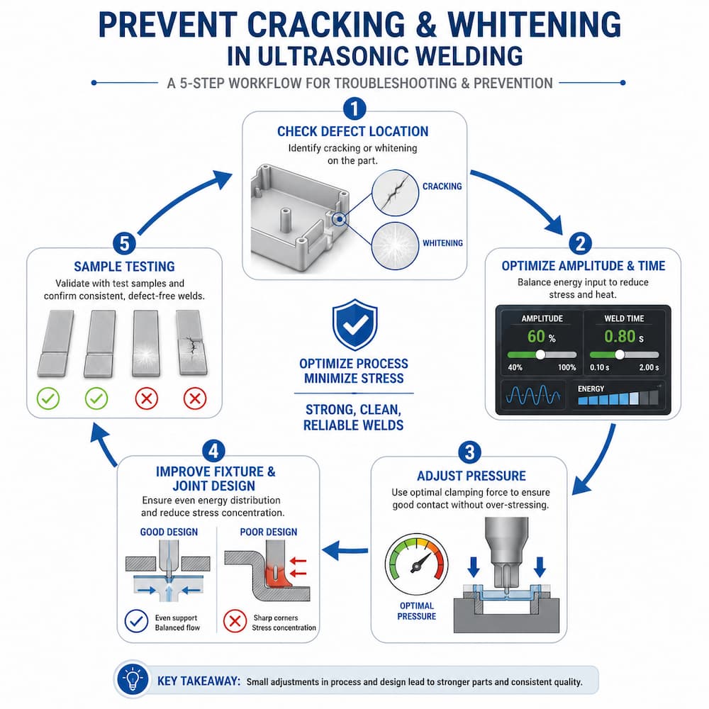
After the process has been optimized, manufacturers should establish a controlled production window.
Recommended controls include:
Upper and lower energy limits
Collapse-distance monitoring
Peak-power monitoring
Stable material and molding specifications
Regular horn and fixture inspection
Defined cleaning and maintenance intervals
Periodic destructive testing
Part traceability by mold cavity and material batch
A servo-driven ultrasonic welding machine can provide more precise control of force, speed, position and
collapse distance for demanding applications.However, a servo machine cannot compensate for poor
joint design, severe molded-in stress or inadequate fixture support.
Q1. Does Stress Whitening Always Mean the Weld Is Weak?
A1: No. Stress whitening is mainly a visible sign of localized deformation. The weld may still have acceptable
strength, but appearance alone cannot confirm structural performance.The part should be tested according
to its actual mechanical or sealing requirements.
Q2. Can Lower Amplitude Eliminate Whitening?
A2: It may help when excessive vibration is the main cause. However, reducing amplitude too far may create
an incomplete or weak weld. Amplitude should be optimized together with weld time, pressure and collapse.
Q3. Which Plastics Are Most Likely to Turn White?
A3: Whitening is often more visible on high-gloss, transparent, dark-colored or stress-sensitive plastic parts.
ABS, PC, PMMA acrylic, PC/ABS and other materials may show whitening depending on grade, geometry
and molding stressNo material should be evaluated by name alone.
Q4. Can Machine Parameters Fix Every Cracking Problem?
A4: No. Parameters can solve defects caused mainly by excessive or unstable energy input.
Cracks caused by sharp corners, poor joint geometry, severe molding stress, material degradation or insufficient
fixture support may require tooling, molding or product-design changes.
Q5. Is a Servo Ultrasonic Welder Better for Cosmetic Plastic Parts?
A5: A servo welder can provide more repeatable force, speed and displacement control, which is useful for delicate or
appearance-sensitive parts.The final result still depends on material, joint design, horn contact, fixture support
and proper process development.
Need Help Identifying the Root Cause?
Plastic cracking and stress whitening should be diagnosed using the actual product, material and weld requirements.
TIMEAST provides ultrasonic welding sample testing, tooling evaluation and process optimization for automotive,
medical, electronics, packaging and industrial plastic components.
Send us:
Plastic samples
Material information
Product drawings
Photos of the defect
Current welding parameters
Strength or sealing requirements
Estimated production volume
Our engineers can evaluate the failure pattern and recommend suitable welding parameters, tooling and equipment
before mass production.
Phone: +86-15989541416
E-mail: sales@sztimeast.com
Whatsapp:+86-15989541416
Add: Building 5, Huixin Intelligent Industrial Park,Guangming, Shenzhen,China 518107
We chat