
sales@sztimeast.com
+86-15989541416
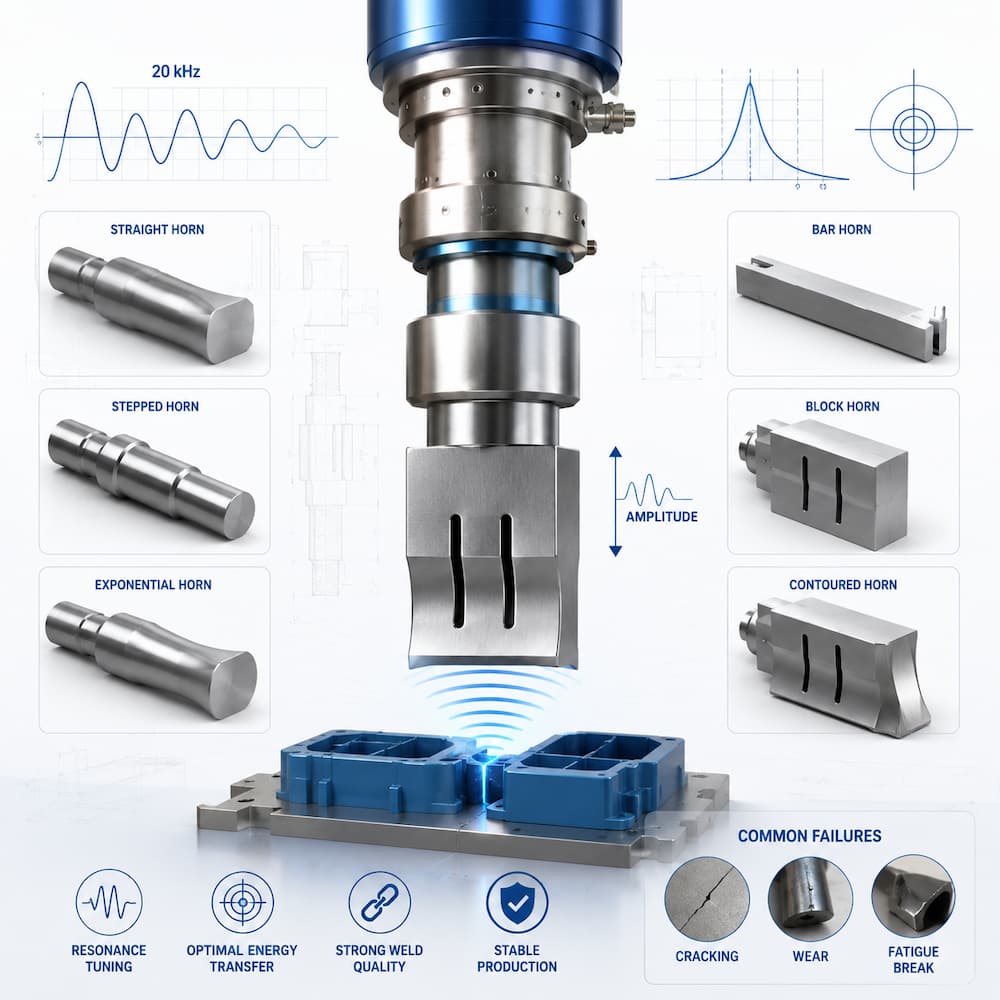
An ultrasonic welding horn, also called a sonotrode, transfers mechanical vibration from
the converter and booster to the plastic part.
A properly designed horn must match the system frequency, provide the required amplitude,
contact the part evenly and withstand repeated production cycles. Poor horn design can cause
weak welds, surface marking, uneven amplitude, high generator load, overheating and cracking.
Common ultrasonic plastic welding frequencies include 15Khz, 20Khz and 35Khz.
Each horn must be designed for the operating frequency of the converter and generator. A 20 kHz
horn cannot be used directly on a 35 kHz system, even when the mounting thread appears compatible.
Horn length is initially calculated according to the acoustic wavelength of the selected material:
Wavelength = acoustic velocity ÷ frequency
Higher-frequency horns are generally shorter. However, the final resonant frequency is also affected by:
horn material
cross-sectional changes
slots and cavities
mounting threads
working-face geometry
coatings and replaceable tips
The finished horn must therefore be measured and tuned after CNC machining. Repair, resurfacing,
wear and coating can also change its frequency.
Incorrect tuning may result in abnormal noise, unstable vibration, excessive current or high generator load.
Horn geometry affects amplitude gain, working area and internal stress.
| Horn type | Typical application | Main consideration |
| Straight horn | Simple flat plastic parts | Low gain and high rigidity |
| Stepped horn | Welding, staking and high-amplitude work | High gain but greater transition stress |
| Exponential horn | Controlled-stress applications | Smoother stress distribution |
| Bar or block horn | Long or large plastic parts | Amplitude uniformity |
| Composite horn | Large or separated welding areas | Multiple working sections |
| Multi-tip horn | Staking, insertion and spot welding | Tip height and amplitude balance |
| Contoured horn | Curved or irregular parts | Accurate product contact |
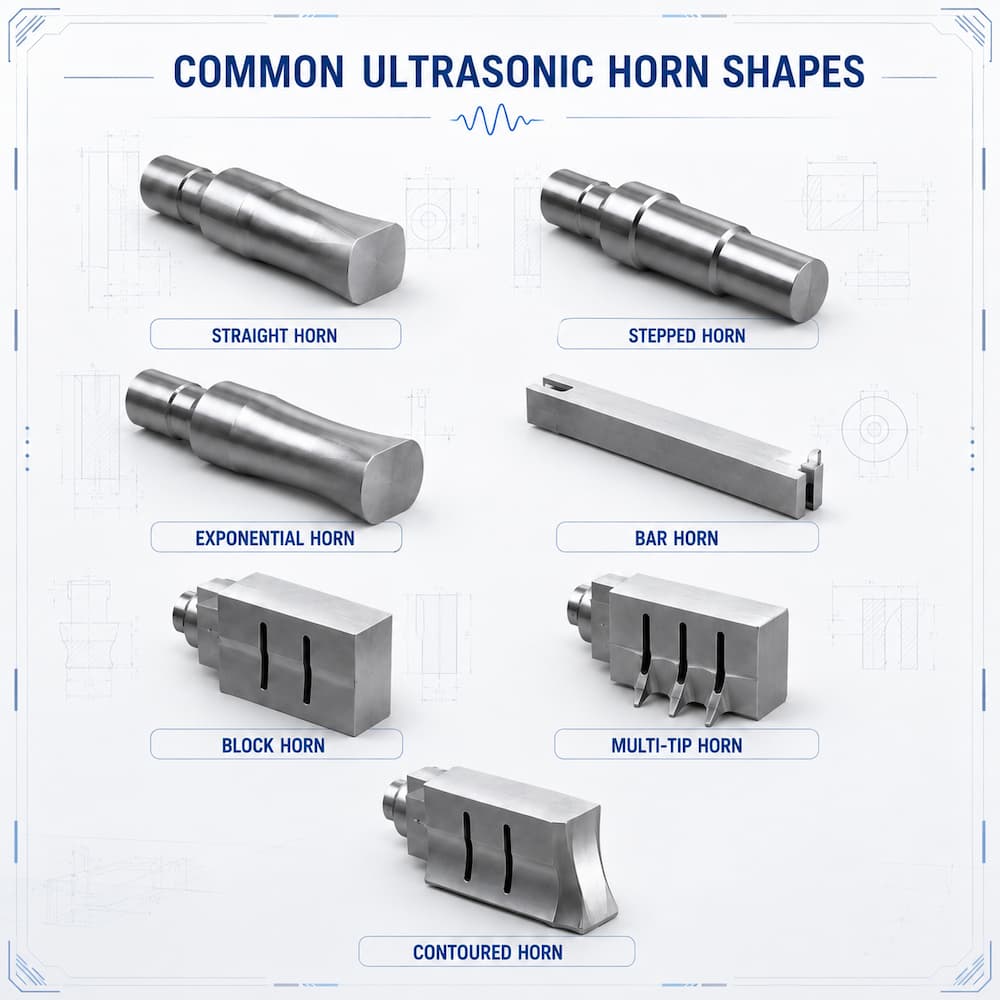
Straight horns are suitable when little amplitude gain is required. They are relatively rigid and simple
to manufacture.
Stepped horns increase amplitude through a change in cross-sectional area. They provide higher gain
but also create greater stress near the transition. Sharp corners should be avoided to reduce the risk
of cracking.
Exponential horns use a smoother change in cross-section. They normally provide lower peak stress
but less gain than stepped designs.
Bar and block horns are commonly used for long or wide products. As horn size increases, maintaining
equal amplitude across the complete working face becomes more difficult.
Slots may be added to control lateral vibration and divide a large horn into narrower vibrating sections.
Slot position, depth and end radius should be determined through analysis and testing.
Composite and multi-tip horns are suitable when several separated areas must be welded at the same time.
Each working point must have consistent height, contact pressure and amplitude.
A contoured horn is machined to match a curved, stepped or irregular product surface.
Accurate contact helps distribute pressure and reduce surface damage. However, deep cavities, thin sections
and sharp transitions can weaken the horn or create unwanted vibration modes.
The horn face must transfer vibration and pressure without damaging the plastic part.
The horn does not always need to cover the entire weld area. Contact should be positioned where vibration
can reach the joint effectively without pressing on unsupported walls, decorative surfaces or fragile components.
Poor contact may cause:
uneven weld strength
part tilting
whitening or dents
excessive flash
inconsistent collapse distance
high generator load
Horn contact should be evaluated together with fixture support and ultrasonic welding joint design.
A smooth face is generally preferred for cosmetic parts. Textured surfaces can reduce slipping but may
leave marks. Knurled surfaces are more suitable for staking, insertion and non-cosmetic applications.
Thin-wall parts require sufficient fixture support. Increasing welding pressure cannot compensate for
poor support or incorrect horn contact.
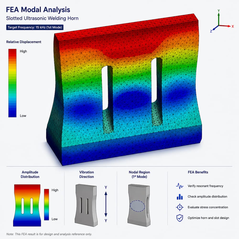
Large horns do not always produce the same displacement at every position.
Uneven amplitude may cause strong welds in the center and weak welds near the edges, or the opposite.
It can also result in inconsistent staking height, local overheating, flash and sealing failures.
Finite element analysis can help evaluate:
resonant frequency
axial vibration mode
lateral or torsional vibration
stress concentration
amplitude distribution
slot geometry
weak sections
FEA is particularly useful for large, asymmetrical, composite and multi-tip horns.
However, simulation cannot replace physical testing. After machining, amplitude should be measured
at several positions across the working face, especially at the center, edges and individual tips.
Aluminum is lightweight, easy to machine and suitable for prototypes and many large horns.
Titanium provides higher fatigue strength and is commonly used for high-amplitude or high-cycle
production.Steel offers high hardness and wear resistance but is generally more suitable for lower-amplitude
applications, staking tips and abrasive materials. For a detailed comparison, see guide to titanium,
aluminum and steel ultrasonic horn materials.
| Problem | Likely cause | Corrective action |
| Horn cracking | Stress concentration or excessive amplitude | Increase radii, reduce gain or redesign the horn |
| Frequency drift | Wear, heat or material removal | Inspect and retune the horn |
| Uneven welds | Poor contact or uneven amplitude | Check contact and measure face amplitude |
| Surface wear | Glass-filled or abrasive plastic | Use coating or a replaceable tip |
| Part marking | Excessive pressure or poor face matching | Correct the contact profile and parameters |
| High generator load | Incorrect tuning or damaged mating surfaces | Inspect and retune the ultrasonic stack |
| Overheating | Poor tuning or excessive production load | Check frequency, connections and cooling |
Cracks commonly begin near sharp corners, deep slots, threads and sudden changes in cross-section.
A cracked horn should normally be replaced because continued operation may damage the booster,
converter or generator.
When welding is uneven, simply increasing amplitude or weld time may over-weld the stronger area.
Horn contact, amplitude distribution, fixture support and molded-part consistency should be checked first.
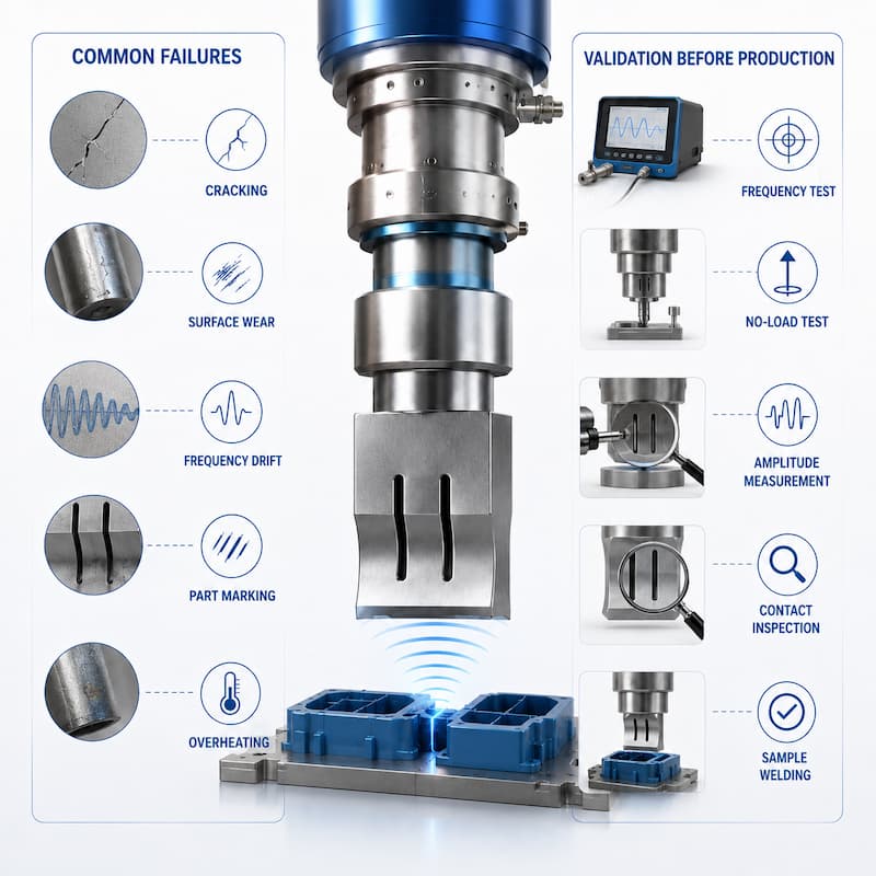
Horn Validation Before Production
A new or modified horn should pass the following checks:
Confirm that the resonant frequency matches the ultrasonic system.
Assemble the converter, booster and horn, then check frequency tracking, generator load, noise
and temperature.
Measure several positions across large, composite and multi-tip horns.
Confirm that the horn contacts the plastic part evenly without pressing on unsupported areas.
Use actual molded parts to evaluate:
weld strength
collapse distance
appearance
flash
deformation
leakage
cycle consistency
A horn may pass the no-load test but still require contact, fixture or parameter adjustments
during actual welding. Ultrasonic welding sample testing can verify the complete process
before equipment production.
Minor face wear may sometimes be corrected by resurfacing, recoating or replacing a removable tip.
The horn should normally be replaced when:
a crack is detected
threads are seriously damaged
deep wear changes the contact profile
frequency becomes unstable
amplitude remains uneven
repeated repairs have removed too much material
Any machining or repair changes the mass of the horn. The repaired horn must be retuned and tested
before returning to production.
A horn supplier normally needs:
3D and 2D product drawings
actual molded samples
plastic material and filler content
weld joint position
required strength or sealing standard
ultrasonic frequency
production cycle
cosmetic requirements
machine and booster information
fixture support details
Actual samples are important because molded parts may differ from the original CAD dimensions.
These inputs allow the supplier to design custom ultrasonic welding horns that match the product
geometry, operating frequency and production requirements.
Conclusion
Ultrasonic welding horn design must balance frequency, amplitude, geometry, contact area and tool life.
Large or irregular horns may require slots, FEA and multi-point amplitude testing. Before production,
the horn should be verified through frequency testing, contact inspection, amplitude measurement and
sample welding.Correct horn design improves welding consistency, reduces generator load and extends
tooling life.
Need a Custom Ultrasonic Welding Horn?
Send us your product drawings, plastic material, welding area and production requirements. TIMEAST
can evaluate the horn geometry, frequency, material and fixture support before manufacturing
Phone: +86-15989541416
E-mail: sales@sztimeast.com
Whatsapp:+86-15989541416
Add: Building 5, Huixin Intelligent Industrial Park,Guangming, Shenzhen,China 518107
We chat