sales@sztimeast.com
+86 159 8954 1416
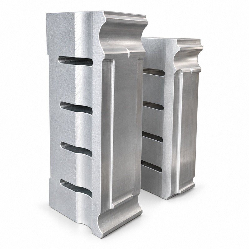
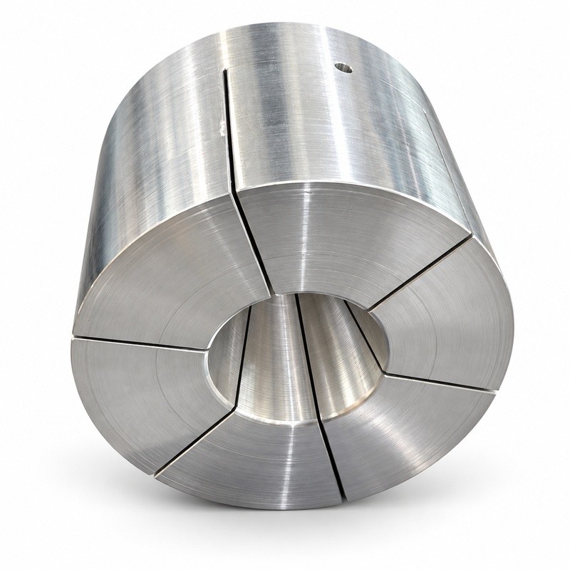
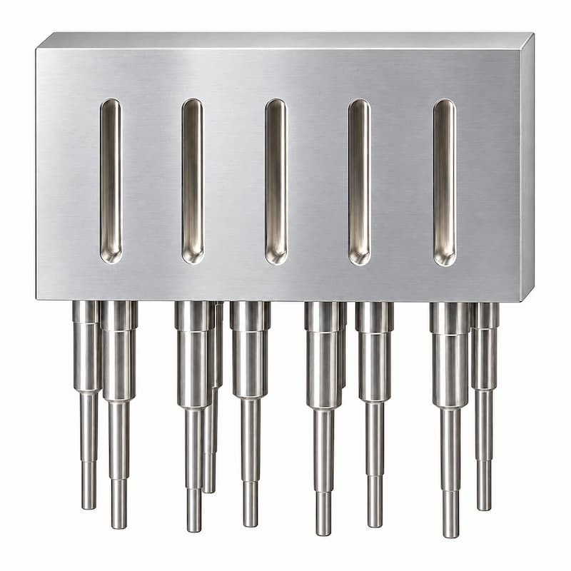
Custom ultrasonic welding horns (sonotrodes) designed around your plastic parts, welding requirements and ultrasonic system.
• Custom shapes and contact profiles based on part drawings or samples
• Titanium alloy, aluminum alloy and steel options
• Frequency and mounting interface reviewed for your machine
• Matching support and positioning fixtures available
An ultrasonic welding horn, also called a sonotrode, transfers mechanical vibration from the ultrasonic stack
to the plastic part. Its working face must suit the part geometry and provide appropriate contact during welding.
TIMEAST supplies custom horns and matching fixtures based on part drawings or samples. Material, geometry,
operating frequency and connection details are reviewed together for the intended application.
See a custom ultrasonic welding horn (sonotrode) in operation with its matching fixture.
The horn geometry and fixture are tailored to the part shape, welding area and application requirements.
Need tooling for your application? Send us your part drawings or photos, plastic material, machine frequency
and welding requirements to discuss suitable horn and fixture options.
Precision-designed for optimal energy transfer
Customized geometry based on product structure
Available in titanium, aluminum, and hardened steel
Tuned to specific ultrasonic frequencies (20kHz, 30kHz, 35kHz, etc.)
High durability and fatigue resistance
Consistent amplitude distribution for stable weld quality
Specifications & Customization
| Parameter | Specification |
| Product | Custom ultrasonic welding horn / sonotrode |
| Material | Aluminum alloy, titanium alloy and steel |
| Frequency options | 15, 20, 28, 35 and 40 kHz, subject to design and system matching |
| Horn geometry | Customized to part geometry, contact area and welding requirements |
| Mounting interface | To be confirmed against the existing booster or transducer connection |
| Customization | customize accordingly to products drawing and samples |
| Matching fixture | Custom support and positioning fixtures available |
| Design inputs | Part drawings or samples, plastic material, welding requirements and machine information |
| Lead time | 4-5 working days after confirming order and material review |
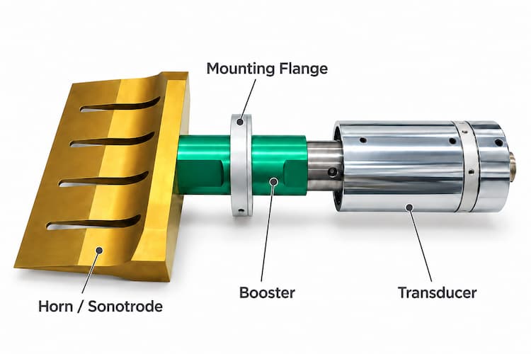
A replacement horn must match more than the nominal operating frequency. The mounting thread,
connection surface, booster configuration and required amplitude also need to be reviewed.
For an existing machine, send us the machine model, operating frequency, booster details and photos or drawings
of the current horn connection. If these details are unavailable, start with clear photos of the machine nameplate
and ultrasonic stack.
For more information on horn geometry and system matching, read our guide to horn design and frequency tuning.
Horn material is selected according to the application, geometry, operating amplitude and production requirements.
• Titanium alloy — suitable for demanding production applications where fatigue resistance and service life justify a higher cost.
• Aluminum alloy — a widely used, cost-effective option for general-purpose applications.
• Steel — considered for applications requiring wear resistance, subject to the horn geometry and operating conditions.
Service life depends on the complete application, including loading, operating conditions and maintenance; material alone
does not determine it.
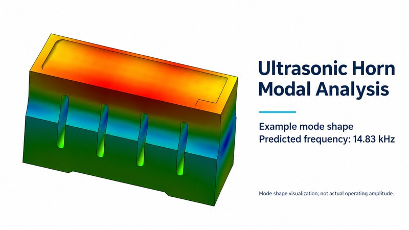
Modal analysis helps assess a sonotrode’s predicted resonant frequency and vibration mode to guide design adjustments.
The manufactured horn is then checked, tuned and tested for its intended application.
Horn geometry is developed around the part surface, weld location and available machine space.
Depending on the application, the design may use a flat or contoured working face, a block or
bar structure, or multiple working points.
The fixture is reviewed together with the horn to support and locate the part during welding.
Final geometry depends on the part design, ultrasonic system and welding requirements.
We can review a replacement horn based on your machine information and existing tooling.
Please provide the operating frequency, mounting connection details, horn photos or drawings,
and part information. Compatibility must be checked before manufacture.
Yes. We can review the design using part drawings or samples, together with the welding requirements
and ultrasonic system information.
The choice depends on the application, horn geometry, operating conditions and budget. We can discuss
titanium alloy, aluminum alloy and steel options after reviewing your requirements.
Photos and drawings can support an initial review. Actual molded samples may be needed to check contact,
fixture support and welding performance. Testing arrangements are agreed for each project.
For a new horn or a replacement, please provide:
Part drawings or photos showing the welding area
Plastic material and required weld result
Machine brand, model and operating frequency
Booster connection details or an existing horn drawing, if available
For replacement horns, describe any cracking, marking or inconsistent welding.
Matching frequency alone does not confirm compatibility.
Use the inquiry form below or contact us on WhatsApp: +86 159 8954 1416.
Phone: +86 159 8954 1416
E-mail: sales@sztimeast.com
Whatsapp:+86 159 8954 1416
Add: Building 5, Huixin Intelligent Industrial Park,Guangming, Shenzhen,China 518107