
sales@sztimeast.com
+86-15989541416
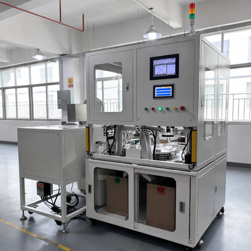
Manufacturers assembling felt or nonwoven components with plastic end caps often use several
separate operations: cutting the felt, loading both parts, positioning them, welding, inspecting
the result and sorting finished components. When production volume increases, manual transfer
between these operations can lead to inconsistent positioning, avoidable handling and unstable
output.
An automatic felt die cutting and ultrasonic welding line integrates these steps into one controlled
process. Roll-fed felt can be cut to the required shape, transferred to a dedicated fixture and welded
to a plastic end cap. Inspection and OK/NG sorting can then be added according to the product's
quality requirements.
This article explains how the process works, when inline die cutting is suitable, when pre-cut felt
feeding may be a better choice, and what information a machine builder needs before developing
a custom system.
It is a customized automation system for assembling felt or nonwoven components with compatible
thermoplastic parts. A typical line may combine:
roll feeding and tension control for felt material;
precision die cutting;
automatic feeding of plastic end caps;
robotic or mechanical part transfer;
dedicated positioning fixtures;
ultrasonic welding;
presence, position or appearance inspection;
OK/NG sorting and automatic unloading.
The exact configuration depends on the product geometry, material behavior, required output and
inspection criteria. It should not be treated as a standard machine that can process every felt and
plastic combination without testing.For a commercial overview of the available customized solution,
see the Custom Felt & End Cap Ultrasonic Welding Line.
Felt or nonwoven material is supplied from a roll and advanced to the cutting station. Stable web tension
is important because stretching, slipping or curling can change the cut position and affect downstream assembly.
Depending on the material, the feeding unit may require guides, tension control, sensors for material presence
and detection of the roll end. The feeding pitch must remain synchronized with the cutting cycle to control
both accuracy and material usage.
The cutting tool produces the required felt shape from the roll. Tool design depends on the material thickness,
density, compressibility and part profile.
Before equipment design is finalized, the supplier should confirm:
whether the cut edge must be visually clean;
allowed dimensional tolerance;
whether loose fibers are acceptable;
scrap-removal method;
cutting-tool maintenance interval;
whether several product sizes require changeable tooling.
A fast cutting cycle alone is not sufficient. The cut piece must also remain flat and stable enough to be picked,
transferred and accurately positioned.
Plastic end caps may be supplied through a vibratory bowl feeder, tray, conveyor or manual loading station.
The correct method depends on part geometry, surface requirements and the risk of parts becoming nested,
scratched or incorrectly oriented.
Sensors can verify part presence and orientation before the end cap enters the assembly fixture. For visible
components, feeding trials should also check whether repeated contact inside a bowl feeder creates
unacceptable surface marks.
After cutting, the felt component is moved to the assembly position. Vacuum pick-up, mechanical grippers
or a dedicated transfer mechanism may be used.
Felt is flexible and can be difficult to handle consistently. Porosity, static electricity, surface fibers and
deformation all influence the transfer method. A gripper that works well with one felt grade may not be
suitable for another, so testing with actual production material is important.
The fixture must control the relative position of the felt and plastic end cap without excessively compressing
or distorting either component.
At the welding station, high-frequency mechanical vibration is applied through a sonotrode while the components
are held under controlled pressure. Localized heat is generated at the joint interface, allowing suitable thermoplastic
material to soften and form the bond.
Welding feasibility depends on more than the machine's power rating. Important factors include:
plastic resin and any fillers or additives;
felt or nonwoven composition;
joint and energy-director design;
contact area and part rigidity;
horn access and support from the lower fixture;
welding force, amplitude, energy, time and displacement limits;
acceptable appearance and required bond strength.
Natural felt and other non-thermoplastic materials do not automatically form an ultrasonic bond by themselves.
The complete material structure must contain a weldable thermoplastic component or another validated bonding
mechanism. Sample testing is therefore necessary before committing to a full automation line.
An inspection station can check characteristics that are visible or measurable with the selected sensors.
Depending on the application, the system may verify:
presence or absence of the felt component;
part orientation;
gross positional offset;
selected dimensions;
visible surface defects;
marking content, if a marking process is included.
Vision inspection does not automatically prove weld strength or hermetic sealing. If the critical requirement
is peel strength, pull strength, leakage or another functional characteristic, the quality plan should include
an appropriate test method and sampling strategy.
Inspection results can be connected to automatic OK/NG sorting so that rejected components do not mix
with qualified output.
Finished parts can be discharged to collection bins, a conveyor or the next production process.
Where traceability is required, the control system may also record cycle counts, alarms, inspection
results and selected welding data.
The required data format, retention period and connection to a factory system should be defined during
the proposal stage rather than added after the mechanical design is complete.
Not every project needs inline die cutting. The best feeding concept depends on how the felt parts are
supplied and how frequently the product changes.
| Decision factor | Roll-fed inline die cutting | Pre-cut felt feeding |
| Incoming material | Felt or nonwoven roll | Individual pre-cut pieces |
| Main benefit | Integrates cutting and assembly while reducing intermediate handling | Can simplify the machine when qualified pre-cut parts already exist |
| Material utilization | Controlled through cutting layout and feed pitch | Determined by the upstream cutting process |
| Changeover | May require cutting-tool, guide adjustments | May require feeder, guide and fixture changes |
| Feeding challenge | Web tension, cut release and scrap removal | Separating, orienting and feeding flexible pieces |
| Typical fit | Stable, high-volume production of one or a few part sizes | Existing supply of pre-cut parts or projects with a different automation layout |
One TIMEAST project used roll-fed felt, inline cutting, an eight-station rotary process and automatic inspection.
See the automated end cap and felt welding case study.
Another project used pre-cut felt feeding and added laser marking for part identification.
See the end cap and felt welding automation line with laser marking.
These are two different production concepts. The correct choice should be based on the customer's actual
incoming material, required cycle time, product range and factory workflow.
Variation in felt thickness, density or flatness can affect cutting, pick-up, positioning and welding.
The material used during sample testing should represent normal production variation, not only
the best samples.
The plastic component must be rigidly supported, and the joint area must provide a controllable
path for ultrasonic energy. A poorly designed joint cannot always be corrected by increasing
amplitude, force or welding time.
The output of an automatic line is determined by its slowest effective station, including inspection,
transfer and unloading—not only the welding time. Required net output should include expected
stoppages, changeovers and reject handling.
If several product models will run on the same line, the supplier needs drawings and forecast volume
for every model. Quick-change fixtures, recipe control and part-identification checks should be
considered during the initial design.
The customer and machine builder should agree on a written OK/NG definition. A camera can only
detect characteristics that are visible, measurable and consistently presented. Functional weld quality
may require destructive testing, force testing or leak testing outside the vision station.
Machine guarding, door interlocks, emergency stops, safety light curtains, electrical standards, available
floor space, power supply, compressed air and upstream/downstream connections should be confirmed
before layout approval.
An integrated felt die cutting and ultrasonic welding line is generally worth evaluating when:
production volume is high enough to justify automated handling;
manual positioning causes unstable quality or labor dependence;
the product and material specifications are reasonably stable;
felt cutting and welding need to operate as one continuous process;
automatic inspection, sorting or traceability is required;
the customer can provide representative samples and clear acceptance criteria.
It may not be the best first step when product design is still changing frequently, annual volume is low,
the joint has not passed feasibility testing, or material variation has not been controlled. In such cases,
a standalone or semi-automatic welding station may provide a lower-risk starting point.
To evaluate a custom system, provide as much of the following information as possible:
2D and 3D drawings of the felt and plastic components;
physical samples of every material and product model;
material specifications, including resin, fillers and felt composition;
current manual or semi-automatic production video;
required net output in qualified parts per hour;
acceptable dimensional and positional tolerances;
required weld-strength, appearance or leakage standards;
inspection items and written OK/NG definitions;
number of product models and required changeover time;
marking, data export or traceability requirements;
available floor space, power supply and compressed-air conditions;
destination country and applicable machine safety or documentation requirements.
Clear input data allows the engineering team to evaluate process feasibility, propose the correct
feeding method and define a realistic automation layout.
Automatic equipment should be developed only after the material combination and welding process
have been evaluated. Sample testing can help determine whether the joint is suitable for ultrasonic
welding, establish an initial process window and identify risks in cutting, feeding and positioning.
If you are evaluating an automatic line for felt or nonwoven components and plastic end caps,
send TIMEAST your drawings, samples and target production requirements. The engineering team
can review the application and recommend a standalone, semi-automatic or fully automatic solution
according to the project requirements.
Phone: +86-15989541416
E-mail: sales@sztimeast.com
Whatsapp:+86-15989541416
Add: Building 5, Huixin Intelligent Industrial Park,Guangming, Shenzhen,China 518107
We chat