
sales@sztimeast.com
+86-15989541416
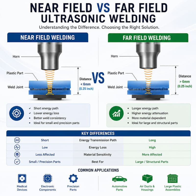
Near-field and far-field ultrasonic welding describe the distance ultrasonic vibration must travel from
the horn contact surface to the weld interface. As a general industry guideline, a weld located about
6 mm (1/4 in.) or less from the horn is considered near-field, while a joint farther than about 6 mm is
considered far-field.
The distinction matters because transmission distance affects amplitude at the joint, material suitability,
process stability and part design. Near-field welding is generally preferred when part geometry allows it,
while far-field welding requires greater attention to material behavior, tooling and process validation.
Near-field ultrasonic welding refers to a welding method where the distance between the horn
contact surface and the welding joint is relatively short, typically less than 6 mm.
In near-field welding, ultrasonic energy is transferred directly to the welding interface with
minimal energy loss.
Near-field welding is preferred whenever the horn can be positioned close to the weld interface,
because the shorter transmission path generally improves energy transfer and process consistency.
For applications requiring precise process control, servo ultrasonic welder can provide improved
welding consistency and parameter management.
Near-field welding can be used with both amorphous and semi-crystalline thermoplastics, although
actual weldability still depends on material compatibility, joint design and part geometry.
Because the welding area is close to the horn, energy transmission is more stable and controllable,
making this method ideal for precision welding applications.
Near-field welding offers several important advantages in plastic assembly applications.
Higher Energy Efficiency
Since the welding interface is close to the horn, ultrasonic energy can be transferred more effectively
with reduced attenuation.
Better Welding Consistency
The shorter transmission distance allows more stable vibration delivery, resulting in more consistent
weld quality during mass production.
Faster Welding Cycles
Near-field welding typically requires less energy and shorter welding times, improving production efficiency.
Reduced Risk of Part Damage
Because energy can be controlled more precisely, the risk of overheating, cracking, or part deformation is lower.
Ideal for Precision Components
Near-field welding is commonly used in products requiring high dimensional accuracy, such as medical devices,
electronic housings, and automotive sensors.
Near-field welding generally refers to applications where the distance from the horn contact surface to
the weld interface is about 6 mm (1/4 in.) or less. Far-field welding refers to distances greater than about 6 mm.
This 6 mm guideline is commonly associated with 20 kHz ultrasonic welding; actual energy transmission also
depends on material, part geometry and operating frequency.
In this process, ultrasonic vibrations must travel through the plastic part before reaching the welding area.
During transmission, part of the ultrasonic energy is absorbed or dissipated by the material.
Far-field welding is generally used when the product structure prevents direct horn access to the weld location.
Far-field applications require careful evaluation of material transmission characteristics, part geometry,
horn design, amplitude, frequency and fixture support. Simply selecting a higher-power welder does not
guarantee a successful far-field weld.
Compared with near-field welding, far-field welding presents more technical challenges.
Energy Loss During Transmission
As ultrasonic vibrations travel through the plastic part, some energy is lost before reaching
the welding interface.
Inconsistent Weld Strength
Uneven energy transmission can result in unstable welding quality and weak bonding.
Surface Whitening
Excessive vibration or internal stress may cause whitening marks on the plastic surface.
Cracking or Part Damage
Improper parameter settings can create stress concentration, leading to cracks or deformation.
Difficulty in Welding Large Parts
Complex geometries and long energy transmission paths may reduce welding efficiency.
Although far-field welding is more difficult, proper process optimization can significantly improve welding quality.
Optimize Joint Design
A properly designed energy director helps concentrate ultrasonic energy at the welding interface.
Reduce the Energy Transmission Distance
Whenever possible, reduce the distance between the horn and the weld area.
Increase Welding Amplitude
Higher amplitude may help compensate for energy loss in long transmission paths.
However, excessive amplitude can increase the risk of surface marking, cracking or unwanted heating,
so amplitude should be established through testing rather than increased arbitrarily.
Improve Fixture Support
A stable fixture reduces vibration loss and improves energy transfer efficiency.
Select Appropriate Frequency
Lower frequencies such as 15 kHz can provide higher available amplitude and may be advantageous
for some larger parts, but frequency should be selected according to material, geometry, weld area and
tooling requirements.
Optimize Welding Parameters
Proper adjustment of welding time, pressure, hold time, and trigger force is essential for stable results.
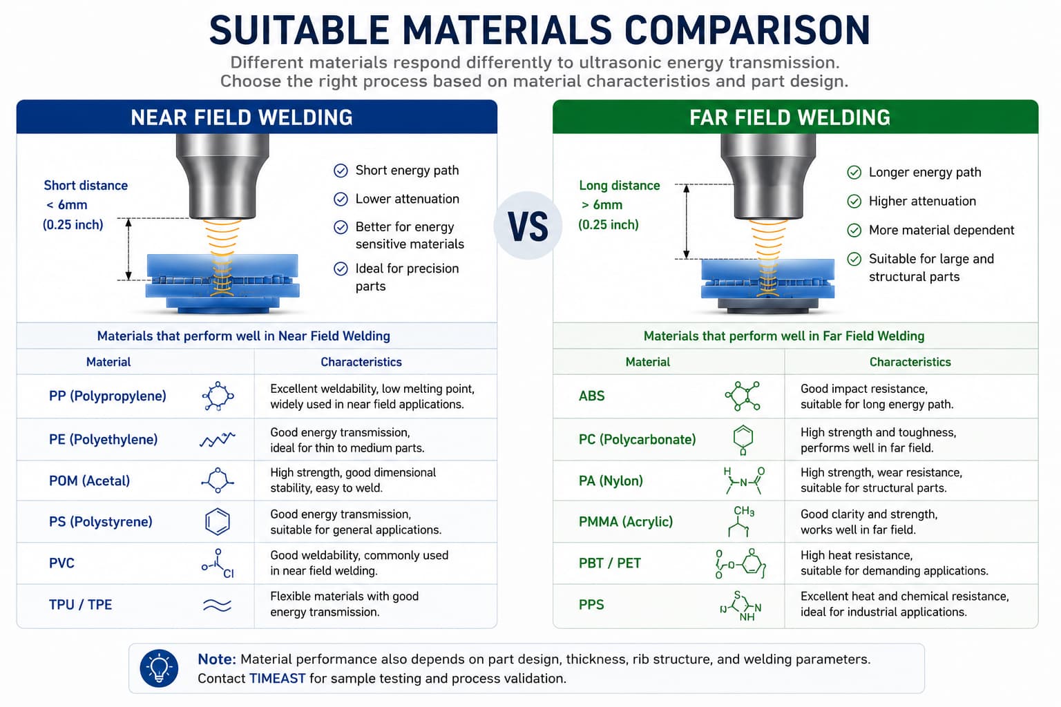
Different thermoplastics respond differently to ultrasonic vibrations.
You can also read What Plastics Are Best for Ultrasonic Welding to compare common materials
such as ABS, PP, PC and PA.
| Material Behavior | Near-field Welding | Far-Field Welding |
Amorphous plastics such as ABS, PC, PS, PMMA | Generally well suited | Generally better suited for far-field energy transmission |
Semi-crystalline plastics such as PP and PE | Often possible with proper design | More challenging because of higher ultrasonic attenuation |
| PA / Nylon | Application dependent | More sensitive to geometry, moisture and transmission distance |
These are general tendencies rather than absolute material ratings. Actual weldability should be validated
using production-grade parts.
Both near-field and far-field ultrasonic welding are widely used in industrial manufacturing.
Weld joint positioned close to the horn contact surface
Thin upper components
Precision housings
Parts requiring efficient energy delivery
Semi-crystalline materials where minimizing transmission distance is importan
Far-Field Typical Part Designs
Recessed weld joints
Deep housings
Parts where horn access close to the joint is impossible
Structures requiring vibration to travel through a significant section of the upper component
Rigid amorphous plastic parts with suitable energy-transmission characteristics
Proper joint design is critical for successful ultrasonic welding.
For more details, see our Ultrasonic Welding Joint Design Guide for Plastic Parts.
Common joint types include:
Energy director joints
Shear joints
Tongue-and-groove joints
Step joints
A well-designed joint helps improve energy concentration, increase weld strength, and reduce
cosmetic defects.
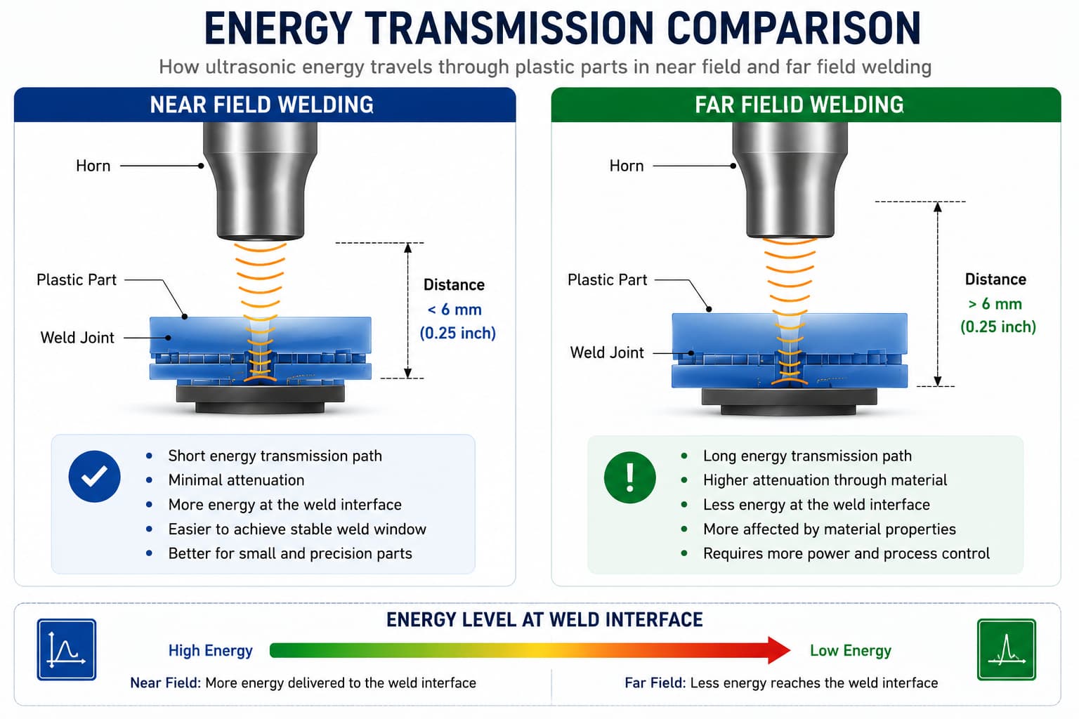
Longer energy-transmission paths can increase the risk of insufficient energy at the joint, inconsistent melting,
part resonance, surface marking or cracking. These issues should be evaluated through part design review and
sample testing.
The selection of near-field or far-field ultrasonic welding depends on several factors:
Material type
Part geometry
Distance to weld interface
Product appearance requirements
Production efficiency requirements
In general, near-field welding provides higher efficiency and better consistency, while far-field welding
is used when structural limitations prevent direct horn access.
Near-field and far-field ultrasonic welding each offer unique advantages and challenges in plastic
assembly applications.
Understanding energy transmission behavior, material properties, and welding distance is essential
for achieving high-quality welds and stable production performance.
With proper joint design, fixture support, and welding parameter optimization, manufacturers can
significantly improve ultrasonic welding quality in both precision and large-scale production environments.
TIMEAST provides sample testing, welding evaluation, and customized ultrasonic welding solutions
for plastic assembly applications.
Phone: +86-15989541416
E-mail: sales@sztimeast.com
Whatsapp:+86-15989541416
Add: Building 5, Huixin Intelligent Industrial Park,Guangming, Shenzhen,China 518107
We chat