
sales@sztimeast.com
+86-15989541416
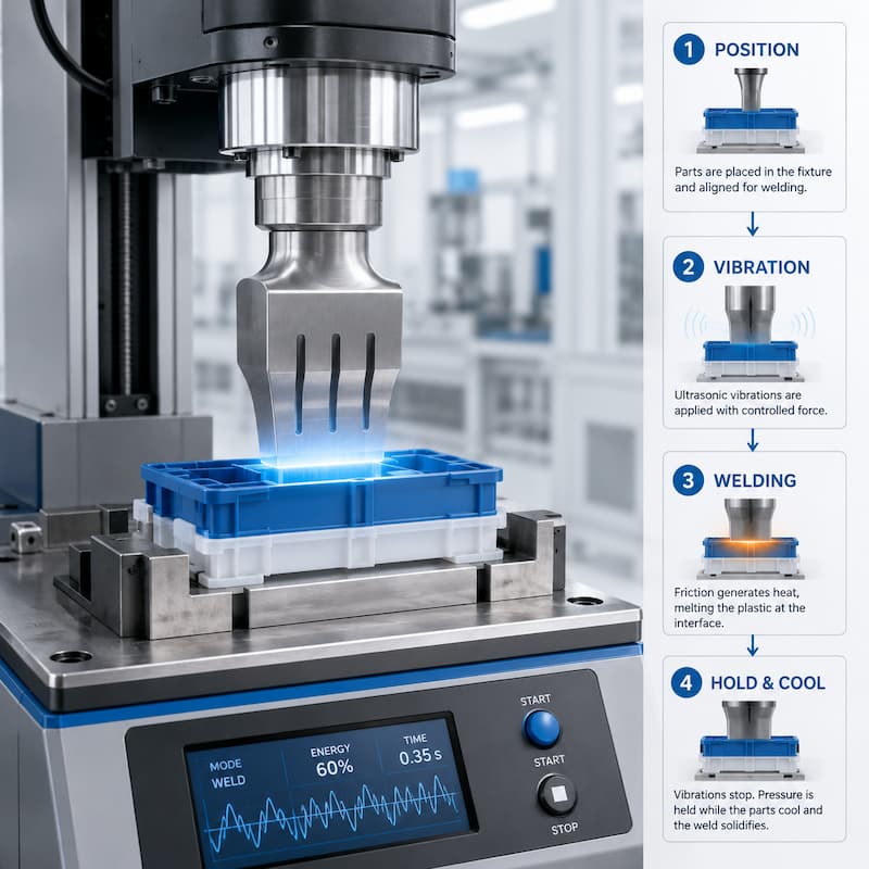
Ultrasonic welding is a fast and repeatable plastic joining process used in automotive parts, medical components,
electronics, filters, packaging and many other plastic products.
However, good welding results do not depend only on the ultrasonic welding machine. The complete welding
processincludes part positioning, fixture support, horn contact, vibration energy, melting control, hold time,
cooling and final inspection.
This guide explains the ultrasonic welding process step by step so engineers, buyers and production teams can
better understand how plastic parts are welded and what factors affect weld quality.
For a complete overview of ultrasonic plastic welding machines, benefits and selection tips, you can also read
our ultrasonic plastic welding guide.
The ultrasonic welding process joins two or more thermoplastic parts by using high-frequency mechanical
vibration. During welding, the ultrasonic horn transfers vibration energy into the plastic parts. The vibration
creates frictional heat at the joint area, causing the plastic to melt and bond together under pressure.
Unlike glue, screws or solvent bonding, ultrasonic welding does not require additional consumables.
The process is clean, fast and suitable for high-volume production. In most production applications,
a complete ultrasonic welding cycle includes:
Plastic part loading
Fixture positioning
Horn contact
Ultrasonic vibration
Plastic melting
Hold time and cooling
Part unloading
Weld strength or appearance inspection
Each step affects the final weld quality. If one step is unstable, the welded part may show weak bonding, flash,
poor appearance, deformation or inconsistent strength.
The first step in the ultrasonic welding process is loading the plastic parts into the welding position.
This can be done manually by an operator or automatically through a feeding system, conveyor, robot or rotary
indexing table. In simple production, operators place the plastic parts into the fixture by hand. In higher-volume
production, automatic loading systems are often used to improve consistency and reduce labor.
Part loading must be stable because incorrect placement can cause welding defects. If the plastic part is tilted,
reversed, not fully seated or placed in the wrong position, the horn may not contact the part correctly.
Common part loading problems include:
Parts not fully seated in the fixture
Wrong part orientation
Unstable manual placement
Plastic parts moving before welding
Part deformation before welding starts
For precision plastic assemblies, sensors, vision inspection or mechanical positioning devices can be added to
confirm that the part is correctly loaded before the welding cycle begins.
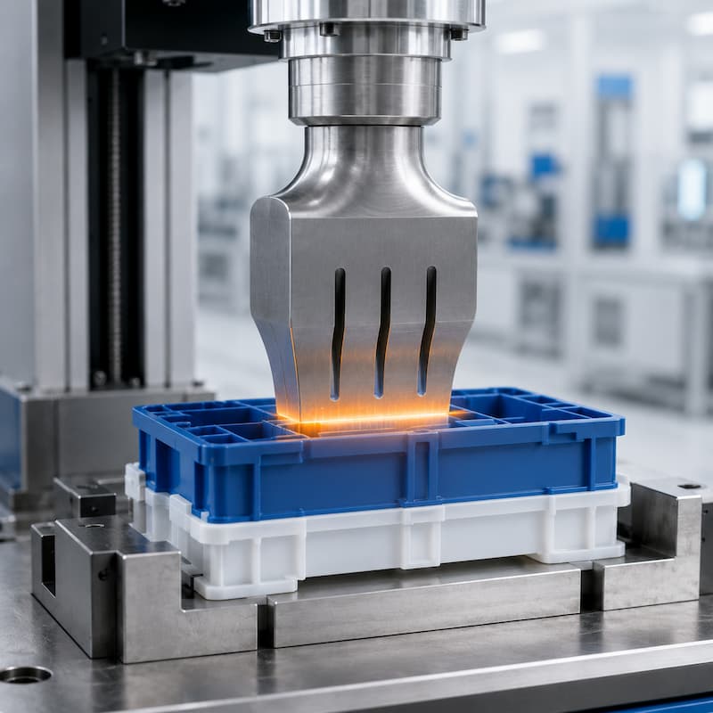
After the plastic parts are loaded, the fixture supports and positions the product during welding.
The fixture, also called the lower tooling or nest, is one of the most important parts of the ultrasonic welding
process.Its job is to hold the plastic part firmly, support the welding area and prevent movement during
ultrasonic vibration.
A good fixture should match the shape of the plastic part and provide enough support under the weld joint.
If the fixturedoes not support the part correctly, ultrasonic energy may be lost, the part may vibrate in the
wrong direction, or the weld may become weak.
Good fixture design helps to:
Keep the part stable during welding
Prevent part movement or tilting
Support thin or flexible plastic areas
Improve welding consistency
Reduce surface marks and deformation
Protect cosmetic surfaces
Poor fixture support is a common reason for inconsistent ultrasonic welding results. Even if the welding
machine is powerful, the weld may still fail if the fixture allows the part to move, flex or absorb too
much energy.
For more information about plastic joint structure and welding support, read our ultrasonic welding
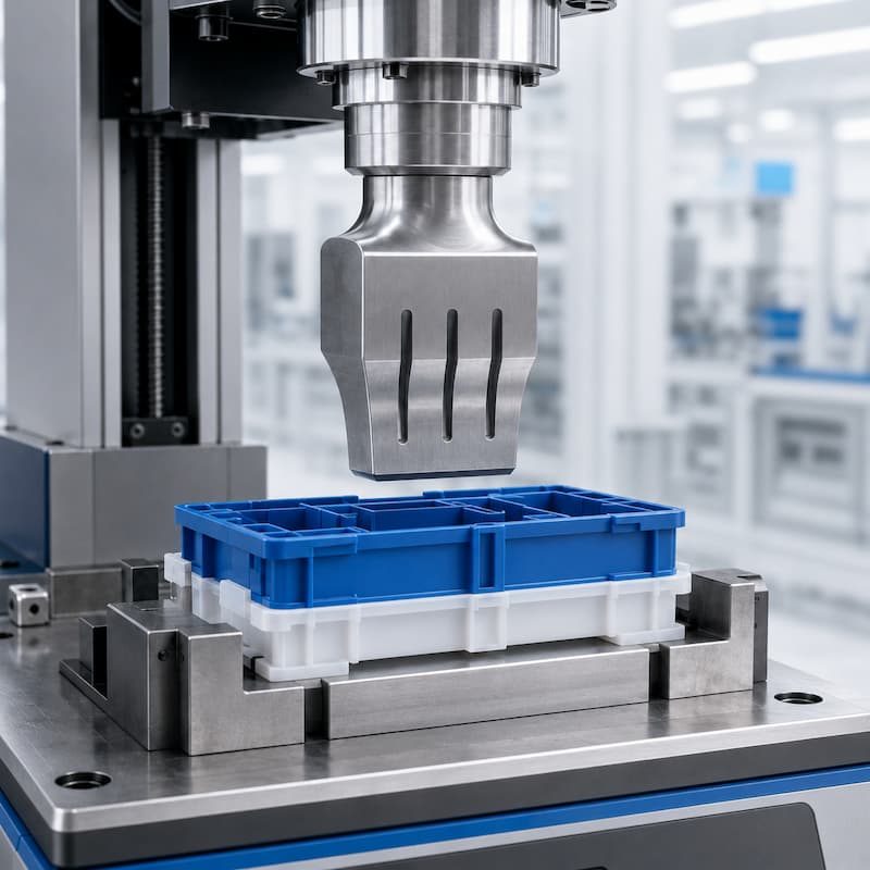
Once the part is positioned, the ultrasonic horn moves down and contacts the upper plastic part.
The horn is the tool that transfers ultrasonic vibration from the transducer and booster into the plastic product.
The contact surface between the horn and the plastic part must be stable, balanced and properly aligned.
Horn contact is critical because ultrasonic energy must enter the plastic part efficiently. If the horn contacts
only one side of the part, the energy distribution may become uneven. This can cause partial welding, flash,
whitening, surface damage or weak bonding.
Important horn contact factors include:
Horn shape
Contact area
Horn alignment
Welding pressure
Part surface condition
Distance from horn to weld joint
The horn should contact the plastic part in a controlled and repeatable way. For cosmetic plastic parts, the horn
surface may need special treatment to reduce marks. For irregular plastic parts, a custom horn design may be
required to match the product shape.
If the horn is not designed or aligned correctly, the ultrasonic welding process may become unstable even
when the machine parameters look normal.
After the horn contacts the plastic part and pressure is applied, ultrasonic vibration starts.The ultrasonic generator
converts electrical energy into high-frequency electrical signals.The transducer changes this signal into mechanical
vibration. The booster adjusts the amplitude, and the horn transfers the vibration into the plastic part.
Common ultrasonic welding frequencies include 15 kHz, 20 kHz, 30 kHz and 35 kHz. The right frequency depends on
the plastic material, part size, welding area, strength requirement and appearance requirement.
During this step, the plastic parts vibrate at very high frequency under controlled pressure. The vibration energy is
focused at the joint area, especially if the plastic part has a proper energy director or designed welding rib.
Key process parameters include:
Frequency
Amplitude
Welding pressure
Welding time
Welding energy
Trigger force
Weld depth
Hold time
The purpose of this step is not to melt the entire plastic part. The goal is to concentrate energy at the joint interface
so that only the intended welding area melts and forms a strong bond.
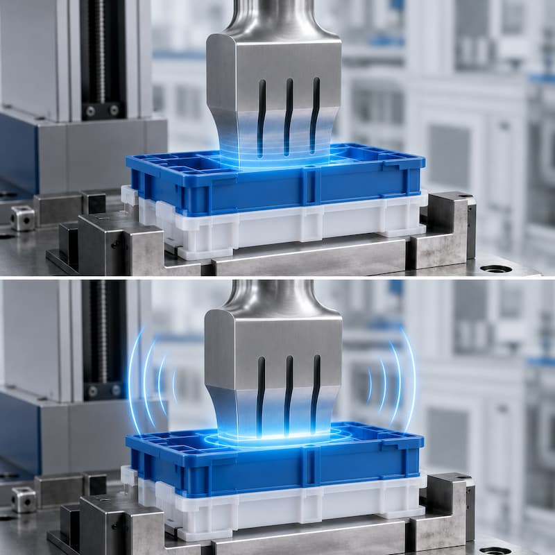
As ultrasonic vibration continues, frictional heat is generated at the plastic joint area. The plastic begins to soften
and melt.This is the key stage of the ultrasonic plastic welding process. The joint design controls where the melting starts.
In many plastic products, an energy director is used to focus the ultrasonic energy into a small area. This allows the plastic
to melt quickly and form a controlled weld.
Good melting control creates:
Strong bonding
Clean weld lines
Short cycle time
Repeatable weld strength
Reduced flash
Better appearance
If melting is not controlled properly, welding defects may appear. Too little energy can cause weak welding or
incomplete bonding. Too much energy can cause flash, burning, deformation or excessive collapse.
Common melting-related problems include:
Weak weld strength
Excessive flash
Uneven weld line
Plastic cracking
Surface whitening
Part deformation
Burn marks
To improve melting stability, engineers usually adjust amplitude, pressure, weld time, energy mode, fixture support
and joint design together instead of changing only one parameter.If your parts show plastic overflow around the weld
seam, read our guide on how to prevent flash in ultrasonic welding.
After ultrasonic vibration stops, the horn continues to press the parts together for a short time. This is called hold time.
Hold time allows the melted plastic to cool and solidify under pressure. This step is important because the weld is still
soft immediately after vibration stops. If pressure is released too early, the parts may separate, shift or form a weak joint.
Hold time helps to:
Improve weld strength
Stabilize the joint
Reduce part rebound
Control final dimensions
Improve repeatability
The correct hold time depends on the plastic material, part size, weld area and strength requirement. Too short a hold time
may cause weak bonding. Too long a hold time may reduce production efficiency without improving quality.
In precision applications, weld depth, collapse distance and hold pressure may also be controlled to improve process stability.
After the weld cools and the horn returns to the upper position, the welded part is removed from the fixture.
Unloading can be manual or automatic. In manual production, the operator takes out the welded part and loads the next
set of parts. In automated production, a robot, gripper, rotary table or conveyor removes the welded product and transfers
it to the next station.
Automatic unloading is useful when the production line requires:
High output
Stable cycle time
Less manual handling
Reduced labor cost
Integration with inspection
OK/NG sorting
Downstream packaging or assembly
For high-volume plastic welding production, ultrasonic welding is often integrated with automatic feeding, assembly,
inspection and sorting systems. This creates a complete ultrasonic welding automation line instead of a standalone
welding station.
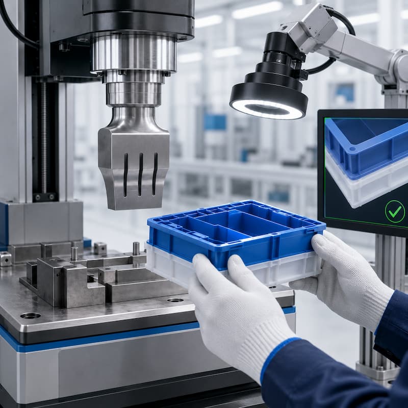
The final step is checking whether the welded part meets quality requirements.Inspection may be simple visual
checking ormore advanced testing depending on the product. For some parts, appearance is most important.
For others, weld strength, sealing performance, pull force, pressure resistance or dimensional accuracy must be tested.
Common ultrasonic weld inspection methods include:
Visual inspection
Pull test
Peel test
Shear test
Leak test
Burst test
Destructive testing
Dimensional inspection
Vision inspection
For production control, many manufacturers define clear acceptance criteria before buying equipment or
starting mass production. This may include weld strength, appearance limits, leakage requirements,
cycle time and defect rate.
If you need to evaluate weld quality, read our guide on how to test ultrasonic weld strength for plastic parts.
A stable ultrasonic welding process depends on the correct combination of machine settings, tooling design
and product design.The most important process parameters include:
Amplitude controls the vibration movement of the horn. Higher amplitude can generate more heat, but
excessive amplitude may cause flash, surface damage or part deformation.
Pressure keeps the plastic parts in contact during welding. Too little pressure may cause poor energy transfer.
Too much pressure may squeeze out melted plastic too quickly and reduce weld strength.
Welding time controls how long ultrasonic vibration is applied. Too short a time may create incomplete welding.
Too long a time may cause overheating, flash or burning.
Energy mode controls the total energy delivered to the weld. This can improve consistency when plastic part
dimensions have small variations.
Trigger force defines when ultrasonic vibration starts after the horn contacts the part. Stable trigger force
helps improve repeatability.
Hold time keeps pressure on the welded joint after vibration stops. It allows the melted plastic to cool and solidify.
For precision applications, controlling weld depth or collapse distance helps ensure consistent bonding and
final part dimensions.
Common Problems During the Ultrasonic Welding Process
Even when the machine is working normally, welding defects may happen if the product design, tooling or
parameters are not suitable.Common ultrasonic welding process problems include:
Weak welds may be caused by poor joint design, insufficient energy, poor fixture support, low amplitude,
incorrect pressure or incompatible materials.
Flash usually happens when too much plastic melts or flows out of the joint area. It may be related to
high amplitude, excessive pressure, long welding time or poor joint design.
Horn marks may appear when the horn contact surface is not suitable, pressure is too high, or the
plastic surface is sensitive.
Inconsistent results may come from unstable part loading, material variation, poor fixture support,
changing part dimensions or unstable process settings.
Burn marks may happen when energy is too high, welding time is too long, air cannot escape from
the joint, or the plastic material is sensitive to heat.
Deformation can be caused by excessive pressure, poor fixture support, thin plastic walls, high amplitude
or overheating.
To solve these problems, manufacturers should not only adjust machine parameters. The best results
usually come from checking the complete welding system, including plastic material, part design,
joint structure, fixture, horn, machine control and inspection method.
Manual Ultrasonic Welding vs Automated Ultrasonic Welding Process
The basic ultrasonic welding process is the same for both manual and automated production. The difference
is how parts are loaded, positioned, welded, inspected and removed.
Manual ultrasonic welding is suitable for:
Low-volume production
Sample testing
Simple plastic parts
Flexible production needs
Lower initial investment
Automated ultrasonic welding is suitable for:
High-volume production
Stable cycle time requirements
Strict quality control
Multi-step assembly
Vision inspection
Automatic OK/NG sorting
Reduced labor cost
Production line integration
In many industrial applications, the ultrasonic welding machine is only one part of the complete solution.
The final system may include automatic feeding, pick-and-place, rotary indexing, ultrasonic welding,
leak testing, vision inspection, laser marking and automatic sorting.
To achieve stable ultrasonic welding results, manufacturers should optimize the entire process instead of
relying only on machine power.Practical improvement methods include:
Use a suitable plastic material combination
Design a proper ultrasonic welding joint
Use a stable fixture with enough support
Make sure the horn contacts the part evenly
Choose the right frequency and amplitude
Control pressure, time, energy and hold time
Check material and part dimensional consistency
Use sample testing before mass production
Define clear inspection standards
Add automation when manual handling causes variation
For new plastic welding projects, sample testing is strongly recommended before final equipment selection.
Testing helps confirm weld strength, appearance, cycle time and machine suitability before production investment.
The ultrasonic welding process is more than simply pressing two plastic parts together with a machine. A complete
welding cycle includes loading, positioning, horn contact, ultrasonic vibration, controlled melting, hold time,
unloading and final inspection.
Each step affects the final weld quality. Stable welding requires the right combination of plastic material, joint design,
fixture support, horn design, welding parameters and inspection method.
For simple parts, a standalone ultrasonic welding machine may be enough. For high-volume or high-precision production,
a customized ultrasonic welding automation system can help improve consistency, reduce labor and control product quality.
If you are not sure whether ultrasonic welding is suitable for your plastic parts, ultrasonic welding sample testing is
recommended before final machine selection. Testing helps confirm weld strength, appearance, cycle time and machine
suitability before production investment.
Phone: +86-15989541416
E-mail: sales@sztimeast.com
Whatsapp:+86-15989541416
Add: Building 5, Huixin Intelligent Industrial Park,Guangming, Shenzhen,China 518107
We chat