
sales@sztimeast.com
+86-15989541416
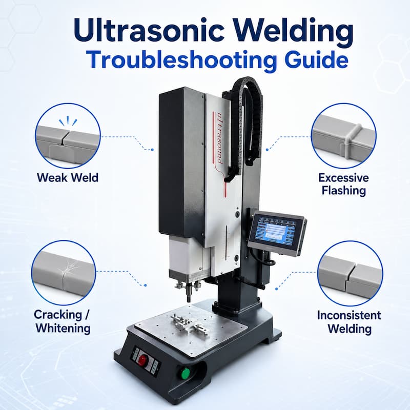
Ultrasonic welding is widely used for joining plastic components in industries such as automotive,
medical, electronics, and packaging. While the process is fast and reliable, issues such as weak welds,
flashing, or inconsistent results can occur during production.
This ultrasonic welding troubleshooting guide explains the most common problems, their causes,
and practical solutions to help you improve weld quality and production efficiency.
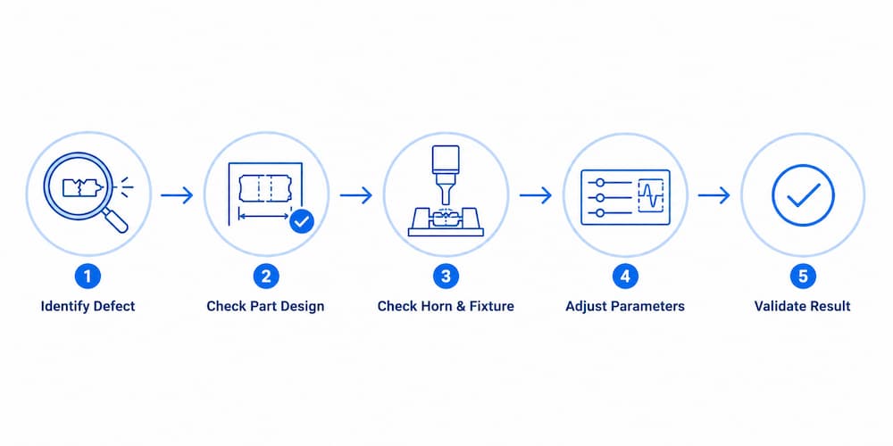
Weak or incomplete welds are one of the most common ultrasonic welding problems. This usually means that
the plastic parts are not receiving enough ultrasonic energy at the joint area, or the energy is not being
transferred evenly through the part.
Common causes:
Low amplitude setting
Insufficient welding pressure
Short welding time
Poor energy director design
Incorrect horn contact
Poor fixture support
Material incompatibility
Contaminated or wet plastic parts
Part movement during welding
Recommended checks:
Check whether the weld is weak on the full joint or only in one area
Inspect the energy director and joint design
Check horn contact surface and alignment
Confirm that the fixture supports the part firmly
Review amplitude, pressure, welding time and hold time
Check whether the plastic material is suitable for ultrasonic welding
Test parts from different batches to confirm material consistency
Solutions:
Increase amplitude gradually if the weld energy is too low
Adjust welding pressure to improve energy transfer
Increase welding time or use energy mode if available
Improve energy director design
Redesign or repair the welding horn if contact is uneven
Improve fixture support to prevent part movement
Clean and dry the plastic parts before welding
Validate the final parameters through sample testing before mass production
Weak welds should not be solved by simply increasing power. If the horn, fixture, joint design or material condition
is not correct, higher power may cause flash, cracking or burn marks without improving weld strength.
Excessive flashing occurs when too much melted plastic is pushed out from the weld joint during
ultrasonic welding. A small amount of flash may be acceptable for some hidden joints, but visible
or uncontrolled flash usually indicates excessive energy, pressure or poor joint design.
Common causes include:
Excessive amplitude
Too much welding pressure
Long welding time
Poor energy director design
Insufficient space for melted plastic flow
Poor fixture support
Incorrect horn contact area
Recommended checks:
Check whether the flash appears on one side or around the full joint
Inspect the energy director size and joint structure
Check horn and fixture alignment
Review amplitude, pressure and welding time settings
Confirm whether the part is moving during welding
Solutions:
Reduce amplitude gradually
Reduce welding pressure if the part is being over-compressed
Shorten welding time or switch to energy mode if available
Improve energy director design
Add proper melt flow space in the joint design
Improve fixture support to prevent part movement
Recheck horn contact surface and alignment
Excessive flash is not always caused by high power alone. In many cases, it is related to joint design,
unstable positioning or incorrect tooling support.
Cracks, whitening or material damage usually occurs when the plastic experiences excessive stress,
vibration or heat concentration during ultrasonic welding. These problems are common on thin-wall parts,
cosmetic surfaces, brittle materials and parts with sharp corners or weak support.
Common causes:
Excessive amplitude
Excessive welding pressure
Long welding time
Poor fixture support
Incorrect horn design
Stress concentration in part geometry
Incorrect horn contact position
Material brittleness or high filler content
Poor control of welding depth
Recommended checks:
Check whether cracks or whitening appear near the weld area, corners or ribs
Inspect the part design for sharp corners, thin walls or weak sections
Check whether the fixture fully supports the welding area
Review amplitude, pressure, welding time and hold time
Check whether the horn is pressing on a weak or unsupported area
Confirm whether the material is suitable for ultrasonic welding
Solutions:
Reduce amplitude gradually
Optimize welding pressure
Shorten welding time if the part is overheated
Improve fixture support under the welding area
Redesign the welding horn or adjust the horn contact position
Modify sharp corners or weak structures if possible
Use servo control for better weld depth control when the part is sensitive
Validate the process with real production samples before mass production
For appearance-sensitive parts, cracking and whitening should not be solved only by reducing power.
The horn, fixture, material and part structure must be checked together.
Inconsistent welding results mean that some parts weld well while others show weak bonding, flash,
deformation or poor appearance under the same machine settings. This is one of the most common
problems in mass production.
Common causes include:
Part dimensional variation
Material batch variation
Unstable air pressure
Poor fixture positioning
Horn and fixture misalignment
Inconsistent trigger force
Worn horn or fixture surface
Unstable generator output
Operator adjustment during production
Recommended checks:
Compare OK and NG parts for dimensional differences
Check whether the parts are positioned the same way every cycle
Inspect fixture wear and part support
Check horn surface condition and alignment
Monitor air pressure stability if using a pneumatic welder
Review welding data such as energy, time, collapse distance and peak power
Confirm whether material batches are consistent
Solutions:
Improve part positioning and fixture support
Replace or repair worn tooling
Stabilize air pressure for pneumatic systems
Use more controlled welding modes such as energy mode or collapse distance mode if available
Use servo ultrasonic welding for applications requiring tighter repeatability
Standardize parameter settings and avoid frequent manual adjustment
Conduct sample testing using parts from different batches
Inconsistent welding is often not a single-parameter problem. It usually comes from the combined effect
of part tolerance, fixture support, machine control and material variation.
Overheating and burn marks occur when too much heat is generated at the weld area or when ultrasonic energy
is concentrated in the wrong location. Burn marks can affect appearance, part strength and product quality,
especially for visible plastic components.
Common causes include:
Excessive welding time
Excessive amplitude
Too much pressure
Poor horn contact
Sharp edges causing energy concentration
Poor joint design
Contaminated plastic surface
Incorrect material combination
Poor heat dissipation around the weld area
Recommended checks:
Check whether burn marks appear at the weld joint or horn contact area
Inspect the part surface for oil, dust or contamination
Check horn contact area and surface condition
Review amplitude, welding time and pressure settings
Check whether the joint design causes energy concentration
Confirm whether the material is overheated or degraded
Solutions:
Reduce welding time
Reduce amplitude gradually
Adjust welding pressure
Improve horn contact surface
Clean plastic parts before welding
Optimize energy director and joint design
Improve fixture support and heat dissipation
Use a more suitable welding mode or lower-energy setting
Test different parameter combinations before mass production
Burn marks should be handled carefully. Simply reducing power may reduce burning, but it can also create
weak welds. The best solution is to balance weld strength, appearance and heat control through proper
parameter testing.
Ultrasonic Welding Parameter Optimization
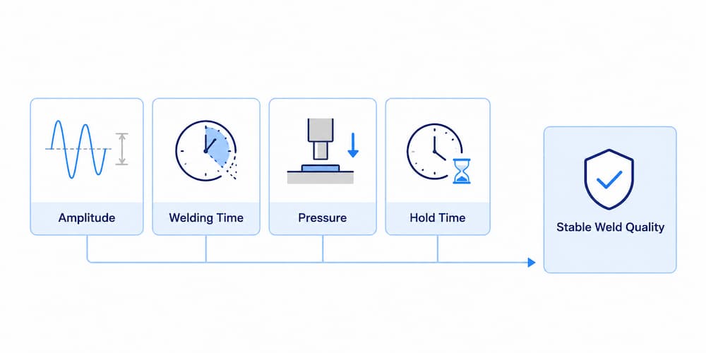
Proper parameter settings are essential for stable welding quality.
Key parameters include:
Amplitude – Controls vibration intensity
Welding Time – Determines heat generation
Pressure – Ensures proper contact between parts
Hold Time – Allows material to solidify
Optimizing these parameters can significantly reduce defects and improve consistency.
How Horn, Fixture and Generator Affect Welding Quality
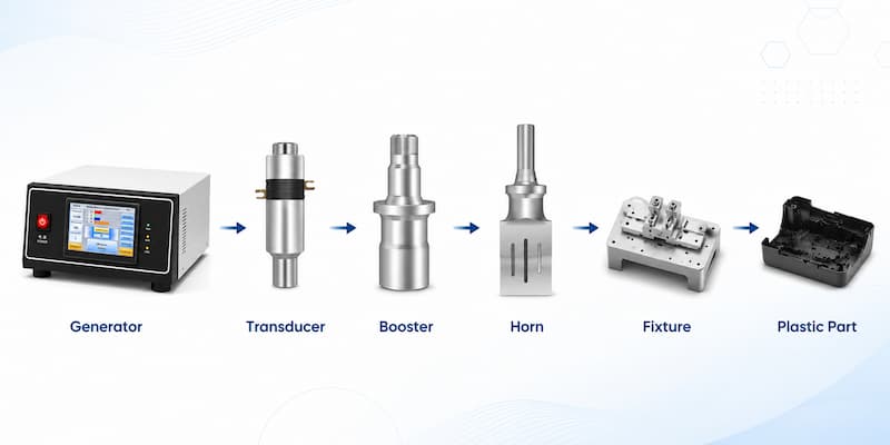
Ultrasonic welding quality depends not only on welding parameters. The horn, fixture, generator and
transducer also directly influence energy transfer, welding stability and repeatability.
A poorly designed, worn or incorrectly tuned welding horn can cause:
Uneven energy distribution
Weak welding areas
Surface marks
Excessive flash
Inconsistent welding results
The horn should match the welding frequency, part shape, contact area and required weld strength.
A proper welding fixture should:
Hold the part securely
Prevent movement during welding
Support the welding area correctly
Keep the part aligned with the welding horn
Reduce vibration loss during welding
Poor fixture support can cause weak welds, cracking, flash and unstable results even when machine parameters
look correct.
Stable ultrasonic output is essential for repeatable welding performance.
The generator, transducer and booster must work as a matched system. Frequency tracking, energy control and
stable output help maintain consistent welding conditions during continuous production.
If the generator output is unstable, or if the transducer and horn are not properly matched, the welding result
may change from part to part.
For complex products or high-volume production, standard machines may not be enough.
Custom automation solutions can provide:
Automatic feeding systems
Multi-station welding
Vision inspection
Automated unloading
These systems improve efficiency, consistency, and production capacity.
Q1: What causes weak ultrasonic welds?
A1: Weak welds are usually caused by low amplitude, insufficient pressure, or incompatible materials.
Q2: How can I improve welding consistency?
A2: Use stable machine settings, high-quality fixtures, and consistent materials.
Q3: What frequency is best for ultrasonic welding?
A3: 15kHz is suitable for large parts, while 35kHz is ideal for precision applications.
Q4: Why does flashing occur in ultrasonic welding?
A4: Flashing is often caused by excessive amplitude, pressure, or overheating.
TIMEAST provides professional support, sample testing, and customized welding solutions.
Phone: +86-15989541416
E-mail: sales@sztimeast.com
Whatsapp:+86-15989541416
Add: Building 5, Huixin Intelligent Industrial Park,Guangming, Shenzhen,China 518107
We chat