
sales@sztimeast.com
+86-15989541416
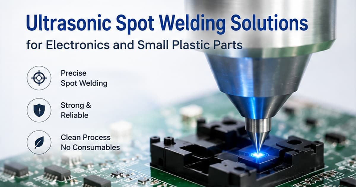
Ultrasonic spot welding is a localized method for joining overlapping thermoplastic parts at
selected points.Unlike conventional ultrasonic welding, which normally uses a molded joint
or energy director,spot welding uses a specially designed tip to concentrate ultrasonic energy
in a small area. The tip penetrates or deforms the upper plastic layer and creates a fused joint
between the overlapping parts.
This process is useful when a complete perimeter weld is unnecessary, when the part is too large
or irregular for a conventional welding press, or when only several localized areas need to be joined.
Ultrasonic spot welding is commonly used for plastic covers, thermoformed parts, insulating sheets,
internal brackets and other assemblies where screws, adhesives or a continuous weld are not required.
This article focuses on ultrasonic spot welding of thermoplastic parts. Welding copper wires,
battery tabs, metal terminals or conductive contacts requires ultrasonic metal welding equipment
and is a different process.
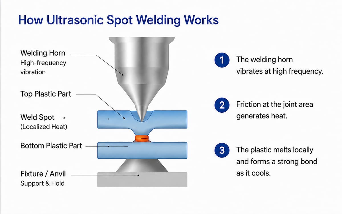
During ultrasonic spot welding, the plastic assembly is placed on a rigid support or anvil. A specially
shaped welding tip contacts the upper plastic layer while controlled force and high-frequency mechanical
vibration are applied.
The vibration creates localized heat at the contact area. The plastic softens, flows and forms a joint with
the lower layer. After the ultrasonic vibration stops, pressure is maintained briefly while the material
cools and solidifies.
A typical welding cycle includes:
Positioning the overlapping plastic parts
Supporting the lower weld area
Bringing the welding tip into contact
Applying controlled pressure
Activating ultrasonic vibration
Reaching the required penetration or energy
Holding the parts while the plastic solidifies
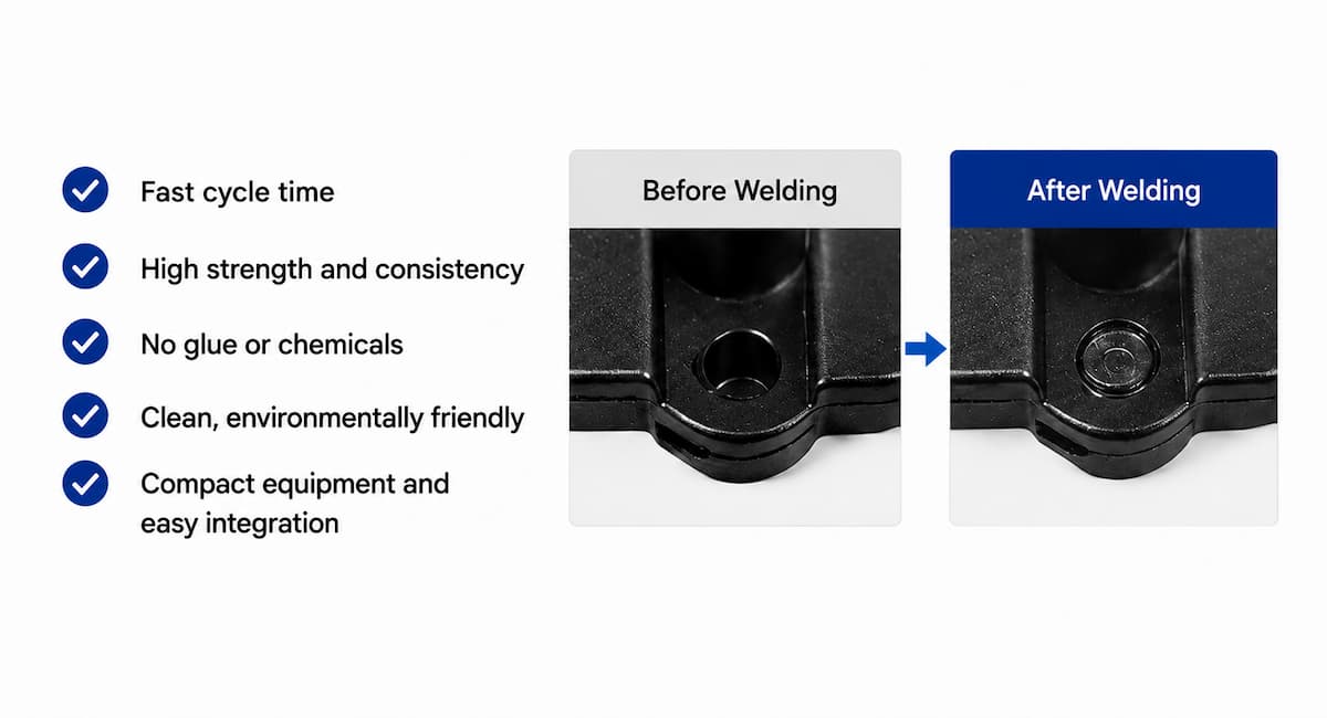
A standard spot weld usually leaves a visible circular or shaped mark on the upper surface.A small raised
ring may also form around the weld point.
This visible mark is a normal characteristic of the process and must be considered when the product has
strict cosmetic requirements.
These three processes use ultrasonic energy, but they do not create the same type of joint.
| Process | How the joint is formed | Typical application |
| Ultrasonic spot welding | A welding tip locally penetrates or deforms overlapping thermoplastic layers | Plastic covers, sheets, tabs and localized joints |
| Conventional ultrasonic welding | Energy is concentrated at a molded joint interface or energy director | Housing halves, sealed enclosures and molded plastic assemblies |
| Ultrasonic staking | A molded plastic post is softened and reformed over another component | Securing PCBs, metal parts,filters or internal components |
For example, forming a plastic post over a printed circuit board is normally ultrasonic staking,
not spot welding.Joining two housing halves along a continuous perimeter is conventional ultrasonic welding.
Spot welding should mainly describe localized joining of overlapping plastic sections.
Typical Applications
Ultrasonic spot welding is suitable for products that require several localized joints instead of one
continuous weld.
Thin plastic covers, insulating sheets and protective layers can be secured at selected points without
screws or adhesives.
Thermoformed or vacuum-formed components often use overlapping plastic sheets without a molded
energy director. Spot welding can join these layers at defined positions.
Localized weld points may be used inside electronic housings where a complete perimeter seal is
unnecessary.Typical examples include:
Internal plastic covers
Small protective housings
Cable guides
Plastic brackets
Insulating components
Communication device parts
The plastic structure can be spot welded, but conductive terminals, wires and antennas require
a separate metal-welding process.For broader electronic plastic assembly applications,
see TIMEAST’s electronics ultrasonic welding solutions.
Automotive Plastic Components
Handheld spot welding may be used for larger automotive trim, plastic covers and interior components
where the complete product is difficult to position under a fixed machine.
Portable spot welders are useful for prototypes, repair work and small production batches where
automation or complex fixtures are not economical.
For broader electronic plastic assembly applications, see TIMEAST’s electronics ultrasonic welding
solutions.
Energy is applied only at the required weld points rather than across the entire assembly.
The ultrasonic cycle is normally short, and there is no adhesive curing time.
Spot welding can reduce separate fasteners, glue, solvents and related assembly steps.
A handheld welding tool can be moved around the product instead of placing the complete assembly
under a large fixed horn.
The process can be operated manually, with a bench-top press or as part of an automated production system.
For many overlapping-sheet applications, the spot welding tip itself concentrates the energy and forms
the localized joint.
Important Limitations
Ultrasonic spot welding is not suitable for every plastic assembly.
Visible Surface Marks
The welding tip normally leaves a visible mark. Spot welding should be located on a hidden surface
when appearance is critical.
Several individual weld points do not create a continuous airtight or waterproof seal.
Products requiring leak resistance normally need a continuous perimeter joint and leak testing.
The lower part must be properly supported. If the plastic flexes during welding, energy may be lost
and the weld may become weak or inconsistent.
With handheld welding, the operator controls the weld location, angle and stability. A fixed press
provides better repeatability.
Ultrasonic heat is localized, but mechanical vibration can travel through the plastic structure. Sensitive
electronic components should be functionally tested after welding.
The correct equipment depends on the part size, weld location, production volume and consistency
requirement.
A handheld ultrasonic welder is suitable when:
The product is large or irregular
Weld points are difficult to access
Production volume is low
The process is used for repair or prototypes
Flexibility is more important than maximum repeatability
The main limitation is operator dependence.
For manual production, see the portable handheld ultrasonic welder.
A bench-top pneumatic machine is more suitable when:
Weld positions must be consistent
A dedicated fixture can be used
Production volume is medium or high
Welding pressure and stroke must be controlled
Process repeatability is important
TIMEAST’s 35kHz 800W ultrasonic spot welding machine is designed for localized welding and
small plastic component applications.
After the welding process has been validated, the station can be integrated with:
Automatic loading and unloading
Rotary indexing tables
Robotic handling
Multiple welding heads
Vision inspection
Presence detection
OK/NG sorting
Production data collection
For high-volume production, the validated welding process can be integrated into custom
ultrasonic welding automation lines with loading, inspection, welding and sorting functions.
Automation should not be designed before the basic welding process is proven stable.
Ultrasonic spot welding is a process type, not a frequency classification.
Depending on the equipment design and application, spot welding systems may operate at 28 kHz,
35 kHz or 40 kHz. Other frequencies may also be used.
In practical applications:
28 kHz is often used for handheld welding, medium-sized plastic components and applications requiring
higher power with compact tooling.
35 kHz is commonly selected for small plastic parts, precision assemblies and compact bench-top equipment.
40 kHz may be considered for very small, thin or delicate components requiring smaller tooling and lower
vibration displacement.
These frequencies are not limited exclusively to spot welding. They may also be used for staking, riveting, inserting
and other localized ultrasonic assembly processes.
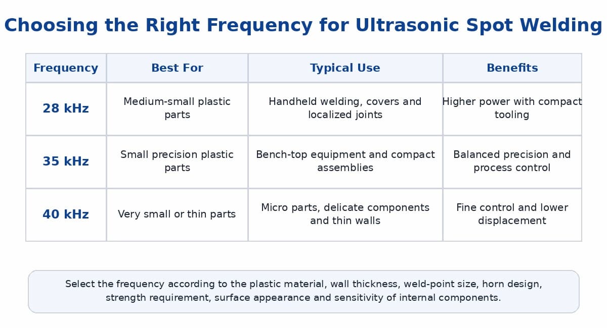
Frequency should be selected according to:
Plastic material
Part thickness
Weld-point dimensions
Required strength
Horn size
Surface appearance
Production method
Internal component sensitivity
For a broader comparison of ultrasonic welding frequencies, read the 15 kHz vs 20 kHz vs 35 kHz
The welding tip and lower support have a major influence on weld quality.
The tip must match the upper-layer thickness, required weld diameter and plastic material.
For more detailed tooling guidance, see the ultrasonic welding horn design guide,
including horn materials, geometry, energy transfer and common failure causes.
A tip that is too sharp may cut the plastic instead of creating a controlled weld.
A tip that is too large may spread the energy over too wide an area.
A tip that penetrates too deeply may damage the lower surface or internal components.
Important tip-design factors include:
Tip diameter
Contact angle
Surface radius
Penetration depth
Plastic thickness
Required joint strength
Acceptable surface mark
The support should be positioned directly beneath the weld point.
It should:
Prevent movement
Maintain consistent part height
Support thin plastic walls
Avoid marking the lower surface
Allow repeatable loading
Resist ultrasonic energy loss
A well-designed welding tip cannot compensate for poor lower support.For repeatable positioning and
stable lower support,learn more about custom ultrasonic welding fixtures designed around the actual
product structure.
A stable spot welding process normally requires adjustment of several related parameters.
Insufficient amplitude may produce a weak or incomplete weld. Excessive amplitude may cause cracking,
excessive penetration or plastic debris.
Too much force may drive the tip too aggressively into the part. Too little force may create unstable contact.
Weld time determines how long vibration is applied. Energy mode may improve consistency when normal
material variation affects the welding time.
The final depth affects both joint strength and appearance. Depth monitoring may be useful for applications
with tight tolerances.
After vibration stops, the tip should remain in position briefly while the softened plastic solidifies.
The correct settings must be established using actual production parts rather than generic parameter values.
Possible causes include:
Insufficient amplitude or weld time
Incorrect tip geometry
Poor material compatibility
Inadequate lower support
Contaminated plastic surfaces
Inconsistent material thickness
Possible causes include:
Excessive amplitude
Long welding time
High force
A tip that is too sharp
Thin upper material
Some material flow around the weld is normal. Excessive flash may indicate too much energy,
excessive penetration or an unsuitable tip profile.
Possible causes include:
High molded-in stress
Brittle material
Excessive amplitude
Welding too close to an edge
Poor support
Sharp corners around the weld area
This is common in handheld production and may be caused by operator variation, worn location marks
or lack of a guiding fixture.
The product requires an airtight or waterproof seal
No visible surface mark is permitted
The lower weld area cannot be supported
The part already has a continuous molded energy director
A plastic post must capture another component
The materials are not ultrasonically compatible
The assembly contains highly vibration-sensitive components
The application involves metal wires or terminals
Depending on the product, conventional ultrasonic welding, ultrasonic staking, heat staking, laser welding,
screws or adhesive bonding may be more suitable.
Product drawings
Plastic material and grade
Upper and lower layer thickness
Weld-point position
Required weld strength
Cosmetic requirements
Internal component information
Production volume
Photos or physical samples
Testing should confirm:
Material compatibility
Welding-tip geometry
Suitable frequency and power
Amplitude and force
Weld time or energy
Penetration depth
Joint strength
Surface appearance
Production repeatability
A successful weld on one sample is not enough. Testing should include multiple parts and normal
production variation.TIMEAST provides ultrasonic welding sample testing before final machine and
tooling selection.
A:Normally, a conventional molded energy director is not required. The dedicated welding tip
concentrates the energy at the selected spot.
A: No. Staking reforms a molded plastic post to retain another component. Spot welding joins
overlapping thermoplastic layers locally.
A: No. Separate weld points normally leave gaps between them. Airtight products require a
continuous sealing joint.
A:There is no universal best frequency. The correct choice depends on the material, thickness,
weld area, tooling and strength requirement.
A: It can be used for low- or medium-volume work, but a fixed or automated machine normally
provides better positional consistency for mass production.
Ultrasonic spot welding is a practical method for joining overlapping thermoplastic parts at selected
locations without screws, adhesives or a continuous welding joint.
It is especially useful for plastic covers, thermoformed parts, insulating layers, irregular assemblies
and hard-to-reach weld positions.
Reliable results depend on more than selecting a machine frequency. The welding-tip geometry,
lower support, material compatibility, amplitude, force and penetration depth must be developed together.
Before purchasing equipment, send TIMEAST your drawings, plastic material, part thickness,
weld-point requirements and production volume for an application review.
Explore the 35kHz ultrasonic spot welding machine.
Send samples for ultrasonic welding testing.
Phone: +86-15989541416
E-mail: sales@sztimeast.com
Whatsapp:+86-15989541416
Add: Building 5, Huixin Intelligent Industrial Park,Guangming, Shenzhen,China 518107
We chat