
sales@sztimeast.com
+86-15989541416
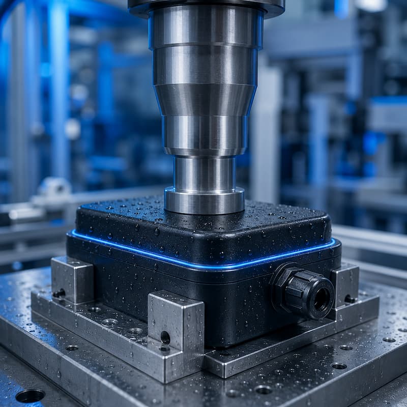
Waterproof plastic enclosures are widely used for automotive sensors, electronic controllers, medical devices,
outdoor equipment, smart locks and other products that must operate in humid, dusty or wet environments.
Ultrasonic welding is often selected because it can join thermoplastic enclosure components quickly without
adhesives, screws or separate sealing materials. When the product, joint, tooling and welding process are
correctly designed, it can create a strong and continuous sealed weld path.
However, ultrasonic welding does not automatically make a plastic enclosure waterproof.
The final sealing performance depends on several connected factors:
Plastic material compatibility
Continuous joint geometry
Molded-part accuracy
Horn and fixture design
Welding frequency and power
Welding force, amplitude and energy
Collapse or weld-depth control
Post-weld cooling
Leak-testing requirements
A stable waterproof enclosure must therefore be engineered as a complete system rather than treated as
a simple welding operation.
Yes. Ultrasonic welding can be used to manufacture watertight and leak-tight plastic enclosures when
the two plastic components are compatible and the weld path forms a continuous closed loop.
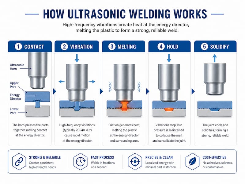
During welding, the ultrasonic horn transfers high-frequency mechanical vibration through the upper
plastic part to the joint interface. A molded energy director or shear-joint feature concentrates the energy
at the intended welding area.
The plastic at the joint interface softens and melts. Under controlled pressure, the molten material flows
across the joint and the two components move closer together. Holding pressure is then maintained while
the material cools and solidifies.
The result is a fused plastic joint without the curing time associated with adhesives.
Ultrasonic welding is especially suitable for production where manufacturers need:
Fast cycle times
Clean assembly without glue
Repeatable weld dimensions
Low material consumption
Automated loading and unloading
Welding data monitoring
In-line leak testing
High-volume production
Nevertheless, a successful weld is not automatically equivalent to a verified waterproof rating. The completed
product must still be tested under its specified operating and environmental conditions.
These terms are frequently used as though they have the same meaning, but they describe different
product requirements.
A waterproof product is designed to resist water ingress under defined conditions. The required protection
level may depend on water depth, exposure time, spray direction, pressure and product orientation.
A watertight enclosure prevents liquid water from passing through the enclosure within a specified
test condition. It does not necessarily mean that no air or gas can pass through the joint.
An airtight enclosure limits air leakage to an acceptable rate. The actual acceptable leak rate must
be defined according to the product volume, test pressure and functional requirement.
Leak-tight is an engineering term that means the measured leakage remains below a specified acceptance
limit. It is more useful than simply describing a product as “sealed.”
Hermetic sealing normally refers to a much stricter gas-tight requirement. The term should not be used
unless a measurable leak-rate standard and suitable verification method have been defined.
An IP rating applies to the complete finished enclosure, not only to the ultrasonic weld.
A welded joint may be continuous and visually acceptable, but the finished product can still leak through:
Cable entries
Connectors
Vents
Buttons
Sensor openings
Screw holes
Gaskets
Overmolded areas
Cracked housing walls
For this reason, a required IP67 or IP68 rating must be verified on the complete assembly under the applicable
test conditions.
Ultrasonic welding joins the plastic components directly. It eliminates adhesive dispensing, curing, storage
and contamination concerns.
This can simplify production and reduce variation caused by inconsistent glue volume, blocked dispensing
needles or insufficient curing time.
The ultrasonic vibration stage usually takes only a short time. Although actual cycle time depends on part loading,
welding, cooling and inspection, the joining process is suitable for high-volume production.
A correctly designed continuous energy director or shear joint can form a complete weld path around the enclosure.
Unlike screws placed at individual points, a continuous weld distributes the seal around the entire perimeter.
Ultrasonic welding equipment can be integrated with:
Automatic loading
Part-presence detection
Vision inspection
Barcode scanning
Welding parameter monitoring
Cooling stations
Air leak testing
Automatic unloading
PASS and FAIL sorting
Modern ultrasonic welders can monitor parameters such as:
Welding time
Welding energy
Peak power
Welding force
Trigger force
Collapse distance
Final weld position
Hold time
These parameters help manufacturers identify abnormal cycles and improve process repeatability.
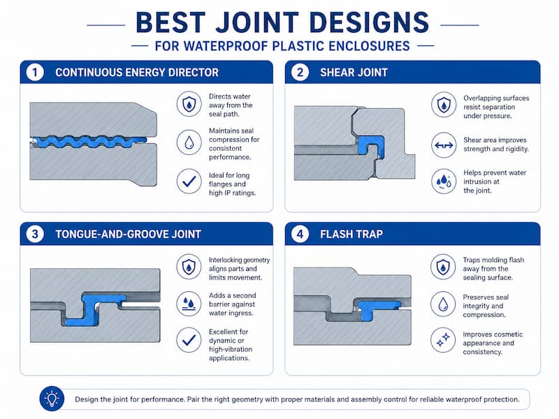
Joint design is one of the most important factors in waterproof enclosure welding.
A waterproof joint must provide a continuous, controlled and supported melt path. A standard
flat-to-flat joint normally does not concentrate ultrasonic energy effectively enough for stable sealing.
The most common joint options are described below.
A continuous energy director is a molded triangular or pointed ridge that follows the complete sealing path.
During ultrasonic welding, its small initial contact area concentrates the vibration energy and begins melting
before the surrounding surfaces.
A continuous energy director is commonly used for:
Small electronic housings
Sensor enclosures
Plastic covers
Filter components
Medical plastic assemblies
Low-pressure containers
The energy director must remain continuous around corners and transitions. Any interruption, damage or
incomplete molding can create a potential leak path.
Energy-director dimensions should be selected according to the plastic material, wall thickness, enclosure size,
molding capability and sealing requirement.
For more detailed design information, see our energy director design guide for ultrasonic welding.
A shear joint uses overlapping vertical surfaces that melt progressively as the parts move together.
It is frequently considered for applications requiring higher structural strength or more demanding
sealing performance.
Advantages of a shear joint can include:
Larger weld area
Controlled material flow
Strong mechanical engagement
Reduced sensitivity to minor surface gaps
Improved sealing potential for suitable geometries
However, shear joints require accurate molded dimensions and proper part alignment. Excessive
interference can prevent assembly or overload the plastic, while insufficient interference may cause
incomplete fusion.
A tongue-and-groove structure helps align the two enclosure halves and can protect the sealing path
from lateral movement.
It may be combined with an energy director to improve:
Part positioning
Joint alignment
Flash control
Internal or external sealing protection
The groove must provide enough space for melt flow and joint collapse. If the structure locks before
the energy director fully collapses, the weld may remain incomplete.
A flash trap provides space for excess molten plastic to flow without becoming visible outside the enclosure.
It is especially useful for products with:
Cosmetic outer surfaces
Tight dimensional requirements
Exposed customer-facing seams
Internal cleanliness requirements
The flash trap should not reduce the supporting wall thickness or create an uncontrolled void next to the sealing line.
Even a properly designed energy director can fail if the surrounding enclosure structure is unsuitable.
Rectangular housings often experience uneven vibration and stress concentration at the corners.
The sealing path should use appropriate radii wherever possible. Very sharp internal or external corners may lead to:
Uneven energy distribution
Incomplete melting
Local cracking
Excessive flash
Unstable collapse
Corner geometry should be evaluated during sample welding and leak testing.
Sudden wall-thickness changes can alter how ultrasonic vibration travels through the part.
A thick section next to a thin wall may produce localized heating, while unsupported thin walls may flex
instead of transferring energy to the joint.
The wall thickness around the welding path should be as uniform as practical.
Screw bosses, ribs and internal supports can change the stiffness of the enclosure.
When placed too close to the weld path, they may create local high-energy areas, resulting in:
Whitening
Cracking
Uneven collapse
Local over-welding
Internal component damage
Connector openings, display windows, buttons and cable exits can reduce enclosure rigidity.
The horn and fixture must compensate for these structural differences so that welding pressure remains
evenly distributed around the joint.
If the upper and lower parts do not contact evenly before welding, one area may begin melting before another.
This may create:
Partial sealing
Unstable weld energy
Excessive local collapse
Visible flash
Random leak-test failures
There is no universal warpage limit for all enclosures. The acceptable flatness and pre-weld gap must be
established according to the part size, joint geometry, fixture support and leak-rate requirement.
The two enclosure halves should have reliable locating features.
Depending only on the welding horn or operator to align the parts can cause joint offset and incomplete fusion.
Alignment features should position the components without restricting the required welding movement.
Printed circuit boards, batteries, sensors, membranes and fragile components may be affected by vibration
or welding pressure.During product development, manufacturers should confirm:
Component clearance
Vibration sensitivity
Fixture support
Welding sequence
Heat exposure
Electrical functionality after welding
In some applications, the enclosure should be welded before sensitive internal components are installed.
In others, the final assembly sequence must be validated through testing.
The two plastic components normally need compatible melting behavior and chemical composition.
Using the same base polymer is usually the safest starting point, although compatible blends may also be weldable.
Material grade, filler content, moisture, colorant and additives can all influence the welding result.
| Plastic material | General welding considerations |
| ABS | Generally transfers ultrasonic energy well and often provides a stable welding window. |
| PC/ABS | Commonly used for electronic and automotive enclosures. Actual weldability depends on the blend and grade. |
| PC | Can produce strong welds but requires good support and controlled stress to reduce cracking or whitening. |
| PP | Weldable, but its semi-crystalline structure and flexible behavior normally require suitable joint design and process optimization. |
| PE | Can absorb more ultrasonic energy and may require greater amplitude, energy or a more appropriate joint design. |
| PA/Nylon | Can be welded, but moisture content may affect melting behavior and weld consistency. Material conditioning may be necessary. |
| POM | Requires controlled processing and accurate alignment. Sample evaluation is important. |
| Glass-filled plastics | Filler content can affect energy transmission, melt flow and sealing continuity. High filler levels may narrow the process window. |
| Elastomeric materials | Soft materials can absorb vibration and may be unsuitable for conventional ultrasonic enclosure welding. |
Do not evaluate material weldability only by the polymer name.
For example, two polypropylene grades can behave differently because of:
Filler content
Recycled content
Melt-flow rate
Impact modifiers
Flame retardants
Color additives
Manufacturing history
Actual molded parts should therefore be tested before the tooling and machine configuration are finalized.
The ultrasonic horn and lower fixture must work together to maintain uniform contact and pressure
around the sealing path.
The horn must contact the upper enclosure without causing excessive local stress.
Important factors include:
Horn contact area
Part geometry
Surface appearance
Welding frequency
Enclosure size
Vibration amplitude
Material stiffness
Internal component protection
A horn that contacts only a small or uneven area can cause the upper housing to flex. This reduces
the energy reaching the joint and may create inconsistent sealing.
Large enclosures may require a contoured horn, composite horn or a different welding process
depending on the weld-path length and part geometry.
The fixture supports the lower component and prevents unwanted movement during welding.
For waterproof enclosures, the fixture should:
Support the area directly below the weld
Maintain stable part position
Prevent enclosure distortion
Avoid interference with connectors or internal features
Provide repeatable loading
Allow easy part removal
Protect cosmetic surfaces
Insufficient support can allow the lower enclosure to flex, which wastes ultrasonic energy and causes
incomplete joint collapse.
Over-constraining the part can also be harmful. The fixture must support the component while still
allowing the intended joint movement.
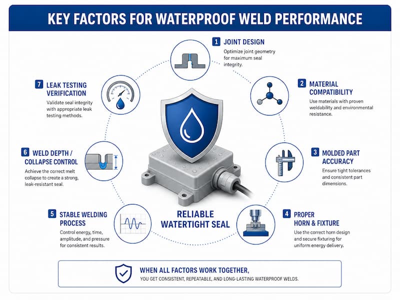
A good enclosure design still requires a stable welding process.
Trigger force determines when ultrasonic vibration begins after the horn contacts the part.
If vibration starts before consistent contact is established, the welding process may vary from cycle to cycle.
A stable trigger condition helps ensure that each weld begins from a repeatable mechanical position.
Amplitude controls the vibration movement delivered by the horn.
Too little amplitude may cause:
Slow melting
Incomplete fusion
High weld-time variation
Leakage
Too much amplitude may cause:
Cracking
Excessive flash
Part marking
Internal component damage
Overheating
The correct amplitude depends on frequency, material, joint design, enclosure size and horn geometry.
Welding force helps transfer vibration and controls molten-material flow.
Insufficient force may reduce energy transfer or create incomplete contact. Excessive force may
suppress vibration, squeeze molten material out of the joint or deform the housing.
Energy mode can help compensate for limited part-to-part variation by continuing the weld until
the programmed energy is reached.
However, energy should not be used as the only acceptance criterion. Two parts can consume similar
energy while producing different joint collapse or sealing results.
Collapse distance measures how far the parts move together as the joint melts.
For waterproof applications, collapse monitoring can be valuable because it relates directly to
energy-director melting and joint formation.
Too little collapse may indicate incomplete fusion. Too much collapse may indicate excessive melting,
flash or dimensional deformation.
Servo-driven ultrasonic welding systems can provide more accurate position and motion control for
applications with tight weld-depth requirements.
Learn more about servo ultrasonic welding machines for precision plastic assembly.
After ultrasonic vibration stops, pressure should remain on the joint while the molten plastic cools and solidifies.
Insufficient hold time may allow the parts to move before the joint becomes stable. Excessive force during cooling
may deform delicate enclosures.
Production systems should use upper and lower limits for important parameters such as:
Energy
Peak power
Welding time
Collapse distance
Final position
Force
Total cycle time
A part outside the established process window should be identified automatically for further inspection.
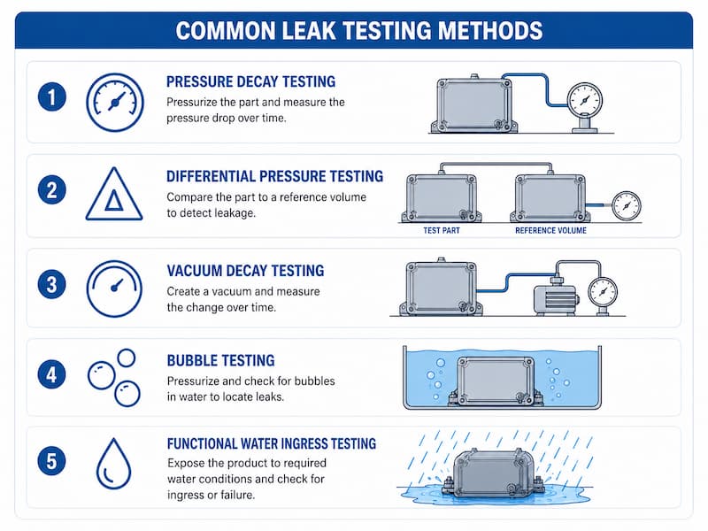
Visual inspection alone cannot confirm that a plastic enclosure is watertight or airtight.
A weld may look continuous while still containing a small channel, crack or incomplete area.
The correct test method depends on:
Product size
Internal volume
Allowable leak rate
Required IP level
Production cycle time
Test pressure
Product strength
Whether the enclosure has a test port
The enclosure is pressurized and isolated from the air supply. The testing system then measures
pressure loss during a defined period.
Pressure decay testing is widely used because it is non-destructive and can be integrated into
automated production.
The test part is compared with a reference volume or reference part.
This method can provide higher sensitivity in applications where temperature, volume and pressure
stability are carefully controlled.
A vacuum is created in the part or test chamber, and the system measures the change over time.
The method may be selected for products that are more suitable for vacuum-based testing than
positive-pressure testing.
The component is pressurized and placed in water or covered with a leak-detection liquid.
Visible bubbles can help locate the leak, making this method useful during process development
and troubleshooting. It is less suitable for fully automated dry production where moisture
contamination is unacceptable.
The finished enclosure is exposed to the required water condition and then inspected for ingress
or functional failure.This method may be needed for qualification but can be slower and less
practical for testing every production part.
IP qualification should be performed according to the required product specification and test conditions.
Passing an air leak test does not automatically prove a specific IP rating unless the correlation between
the leak-test limit and the required water-ingress performance has been established.
For production quality control, manufacturers normally define an air leak-test limit based on validated samples.
Read more about why air leak testing is essential after ultrasonic welding.
When a welded enclosure fails testing, use our guide to identify ultrasonic welding leak-test failure causes and solutions.
The most common causes include:
Damage, molding defects or discontinuity along the energy director can leave an open leak path.
Warpage or dimensional variation causes some sections to weld before others.
Part movement or flexing reduces the energy delivered to the joint.
Insufficient amplitude, time, energy, force or collapse can prevent complete fusion.
Excessive energy or amplitude can create cracks, flash, thin sections or joint distortion.
Offset between the two housing components may cause only part of the energy director to melt.
Changes in moisture, filler, recycled content, colorant or molding conditions can affect the welding response.
The ultrasonic joint may be acceptable while the complete product leaks through a connector,
vent, cable opening, gasket or damaged wall.
These causes should be separated during troubleshooting. Adjusting welding parameters cannot
solve leakage caused by an opening elsewhere in the product.
Ultrasonic welding is commonly evaluated for waterproof or leak-tight plastic products in the following industries.
TPMS sensor housings
Camera housings
Lighting modules
Electronic control housings
Fluid-related plastic components
Exterior sensor enclosures
Battery-related components
These products may need to tolerate vibration, humidity, dust, pressure variation and temperature cycling.
Smart-lock housings
Wireless controllers
Outdoor sensor housings
Chargers and adapters
Tracking devices
Small communication products
Electronic control modules
Ultrasonic welding can reduce enclosure size because it does not require wide screw flanges
or a separate adhesive path.
Diagnostic cartridges
Fluid manifolds
Filter housings
Sensor enclosures
Disposable plastic assemblies
Small reservoirs
Material traceability, particle control, sealing consistency and process validation may be particularly
important for medical applications.
Weather sensors
Flow-monitoring components
Control boxes
Sealed switches
Instrument housings
Small fluid-handling parts
Wearable-device housings
Personal-care products
Small appliance enclosures
Outdoor accessories
Rechargeable product housings
Ultrasonic welding is not suitable for every waterproof enclosure.
Another joining method may be more appropriate when:
The enclosure is too large for stable ultrasonic energy distribution
The weld path is extremely long
The plastic materials are incompatible
The joint cannot form a continuous closed loop
The product must be opened for repair
Sensitive internal components cannot tolerate vibration
The enclosure geometry cannot be supported by a fixture
Optical surfaces have extremely strict cosmetic requirements
The material absorbs excessive ultrasonic vibration
The required sealing area cannot be reached by the horn
Possible alternatives include:
Laser plastic welding
Hot-plate welding
Vibration welding
Infrared welding
Adhesive bonding
Gasket sealing
Mechanical fastening with a gasket
Heat staking for non-sealing assembly areas
The best process should be selected according to the product size, material, geometry, appearance,
production volume and sealing requirement.
Before requesting an ultrasonic welding evaluation, prepare the following information:
2D or 3D drawings
Overall enclosure dimensions
Plastic material and exact grade
Wall thickness
Joint design
Molded-part samples
Internal component layout
Waterproof or airtight requirement
Target IP rating
Test pressure
Allowable leak rate
Exposure time
Operating temperature
Expected product lifetime
Required cycle time
Daily production volume
Manual or automatic loading
Traceability requirements
In-line leak-testing requirement
PASS/FAIL sorting requirement
Available factory air and power supply
Visible weld line
Allowed flash
Surface marking limits
Part color
Transparent or polished areas
Critical dimensions after welding
Sample testing should be completed before the product mold, horn, fixture and production machine
are finalized whenever possible.
TIMEAST provides ultrasonic welding sample testing to evaluate material compatibility, joint design,
welding quality, sealing risk and suitable equipment configuration.
A: Ultrasonic welding can be used as part of an IP67 or IP68 enclosure design. However, the rating applies to
the complete finished product and must be confirmed under the required test conditions. Welding alone
does not guarantee an IP rating.
A: A continuous energy director and a shear joint are commonly considered. The best choice depends on
the material, enclosure size, wall thickness, molding tolerance, sealing requirement and available joint space.
A: Yes, many polypropylene parts can be ultrasonically welded. PP normally requires a suitable joint design,
sufficient energy input and stable fixture support. The exact material grade should be tested.
A: Some compatible plastic combinations can be welded, but similar melting behavior and chemical
compatibility are important. Using the same base polymer is generally the safest starting point. Samples
should be tested before production.
A: Not necessarily. Preventing water ingress and meeting a specified air leak rate are different requirements.
The acceptance standard and test method should be defined for the application.
A: No. Visual inspection can identify obvious flash, cracks or misalignment, but it cannot reliably detect
micro-leaks. Leak testing or functional ingress testing is required when sealing performance is critical.
A: It depends on product risk and quality requirements. For safety-critical, high-value or sealing-sensitive
products, 100% in-line leak testing may be appropriate. Other products may use validated sampling plans.
A: Not always. A pneumatic welder may produce reliable results for stable products with an adequate
process window. Servo systems are useful when precise motion, weld depth, force control and data
traceability are required.
A: It is possible if the components are sensitive to vibration or insufficiently supported. Component position,
horn contact, fixture design and welding parameters should be evaluated during product testing.
A: The most reliable method is to review the drawings, material grade, joint design and sealing
requirement,followed by sample welding and leak testing.
Ultrasonic welding can provide a fast, clean and repeatable method for manufacturing waterproof
plastic enclosures, but the sealing result depends on much more than the welding machine.
A reliable enclosure requires:
Compatible material + continuous joint + accurate molding + correct tooling + controlled welding
+ verified leak testing
The waterproof requirement should be considered during the initial product-design stage rather than after
the mold has already been completed.
Early evaluation allows engineers to improve the joint geometry, reduce leakage risk, choose the correct
welding equipment and establish a realistic production quality-control method.
Send TIMEAST your product drawings, material information, target IP rating, production volume and
available samples.Our engineers can help evaluate:
Material weldability
Joint-design feasibility
Suitable welding frequency and power
Horn and fixture requirements
Servo or pneumatic machine selection
Welding parameter development
Leak-testing requirements
Automation-line integration
Send your samples for ultrasonic welding testing or contact TIMEAST for a customized waterproof
plastic enclosure welding solution.
Phone: +86-15989541416
E-mail: sales@sztimeast.com
Whatsapp:+86-15989541416
Add: Building 5, Huixin Intelligent Industrial Park,Guangming, Shenzhen,China 518107
We chat